Cartridge receiver welding method and clamp applied to same

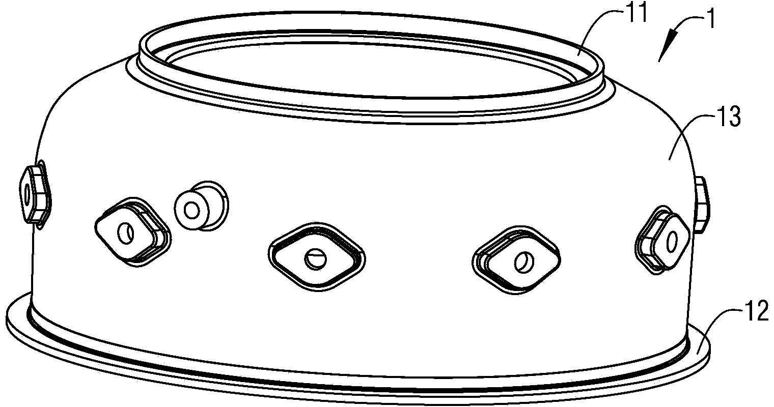
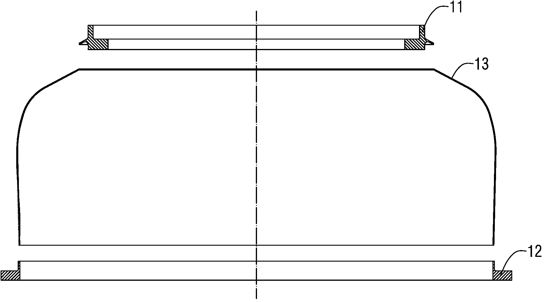
A welding method and welding jig technology, which are applied in welding equipment, welding equipment, auxiliary welding equipment and other directions, can solve the problems such as wrinkling of the casing wall 13 into a wave shape, collapse of the upper mounting edge 11, deformation of the casing 1, etc.

Active Publication Date: 2014-11-26
HUNAN SOUTH GENERAL AVIATION ENGINE CO LTD
View PDF6 Cites 39 Cited by
  • Summary
  • Abstract
  • Description
  • Claims
  • Application Information

AI Technical Summary

Problems solved by technology

Therefore the whole welding process is a key technology, because the thickness of the casing wall 13 is very thin, so the casing 1 is easily deformed during the welding process, and in addition, the welding always produces longitudinal shrinkage and lateral shrinkage, while the upper installation The welding joint form of the side 11 is a hole-axis fit, so the upper mounting side 11 is prone to collapse after welding. Therefore, if the size control of the welding process is not strict, the casing wall 13 is likely to wrinkle and become wavy after welding , so that the profile of the casing 1 does not meet the design requirements

Method used


Image

  • Cartridge receiver welding method and clamp applied to same
  • Cartridge receiver welding method and clamp applied to same
  • Cartridge receiver welding method and clamp applied to same

Examples


Embodiment Construction

[0048] In order to have a clearer understanding of the technical features, purposes and effects of the present invention, the specific implementation manners of the present invention will now be described with reference to the accompanying drawings. Wherein, the same parts adopt the same reference numerals.

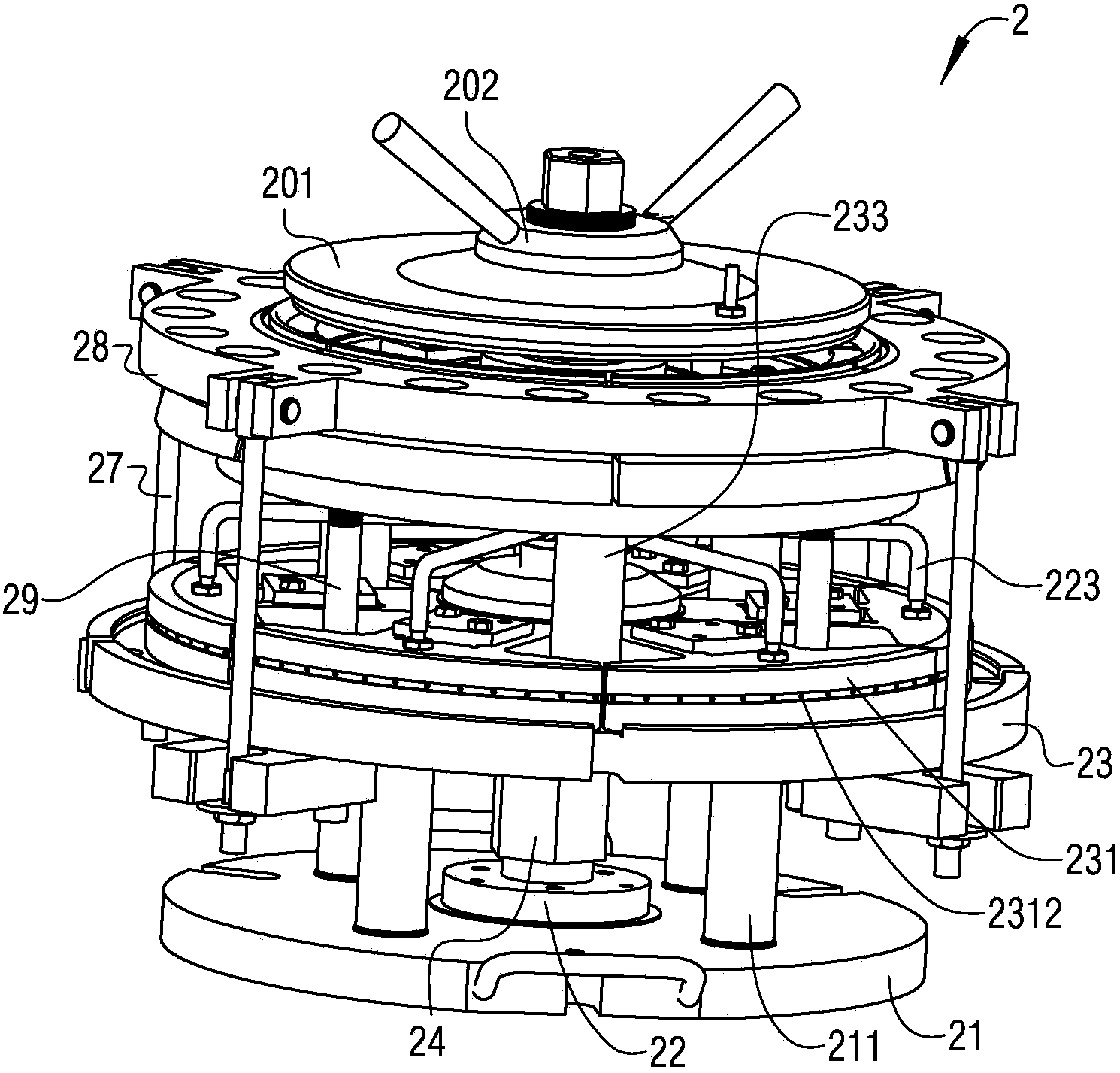
[0049] figure 1 What is shown is a schematic diagram of a three-dimensional structure of a casing for an aero-engine; figure 2 for figure 1 Partially exploded structure sectional view of the shown casing; image 3 Shown is a three-dimensional schematic diagram of the assembled state of the first welding jig provided by a casing welding method according to a specific embodiment of the present invention; Figure 4 Shown is image 3 The three-dimensional structural schematic diagram of the exploded state of the first welding fixture in ; Figure 5 Shown is Figure 4 The schematic diagram of the partially decomposed three-dimensional structure in ; Figure 6 Shown is ...


PUM

PropertyMeasurementUnit
thicknessaaaaaaaaaa

Abstract

The invention provides a cartridge receiver welding method. The cartridge receiver welding method includes the following steps that during installation, it is guaranteed that an upper installation side and a lower installation side are higher than the wall of a cartridge receiver by 0-0.2 mm; manual argon arc welding positioning welding is conducted, and weld joint rolling and profile correction are conducted by a bench worker; through automatic argon arc welding and weld joint rolling and profile correction which are conducted by the bench worker, punching is conducted at the positions, to be welded and corresponding to twelve bosses, of the wall of the cartridge receiver through laser cutting; manual argon arc welding positioning welding is conducted on the twelve bosses, weld joints are leveled by the bench worker, and it is guaranteed that the bosses at the butt joint positions are higher than the wall of the cartridge receiver by 0-0.2 mm; manual argon arc welding is conducted on the twelve bosses; weld joints are leveled by the bench worker, the profile tolerance of a part is corrected, and it is guaranteed that gaps between the part and a model is not larger than 0.5 mm; welding of the cartridge receiver is completed. According to the cartridge receiver welding method, welding deformation can be well controlled, and therefore it is guaranteed that the size and the profile tolerance of the finished cartridge receiver meet requirements. The invention further provides a special clamp applied to the welding method.

Description

technical field [0001] The invention relates to a processing method for aero-engine parts, in particular to a welding method for a casing of an aero-engine. The invention also provides a special fixture for the welding method. Background technique [0002] figure 1 What is shown is a schematic diagram of a three-dimensional structure of a casing for an aero-engine, figure 2 for figure 1 Partially exploded sectional view of the receiver shown, see Figure 1-2 As shown, the casing 1 is a typical thin-walled welded part, which is welded and combined by the upper mounting edge 11, the lower mounting edge 12 and the casing wall 13, and the thickness of the casing wall 13 is only 0.8mm. Two kinds of bosses need to be welded on the casing wall 13 and totally 12 pieces. Therefore the whole welding process is a key technology, because the thickness of the casing wall 13 is very thin, so the casing 1 is easily deformed during the welding process, and in addition, the welding alwa...

Claims


Application Information

Patent Timeline
Patent Type & Authority Applications(China)
IPC IPC(8): B23K37/053
CPCB23K9/16B23K37/0443
Inventor 邓春珍单廷臣赵李军曾旭辉周成王超林胡建
Owner HUNAN SOUTH GENERAL AVIATION ENGINE CO LTD
Why Eureka
Try Eureka