Disc-type micropore aerator
A technology of microporous aerators and aerators, which is applied in water aeration, chemical instruments and methods, sustainable biological treatment, etc., and can solve problems such as pollution of ventilation pipes
Inactive Publication Date: 2014-11-26
GUANGXI NANNING ZHONGJIA ENVIRONMENTAL PROTECTIONVALVE MFG
View PDF3 Cites 2 Cited by
- Summary
- Abstract
- Description
- Claims
- Application Information
AI Technical Summary
Problems solved by technology
[0004] The present invention is to overcome the technical defect that the ventilation pipe is polluted as the sewage enters the ventilation pipe in the above-mentioned prior art, and invents a disc-type microporous aerator
Method used
View moreImage
Smart ImageViewing Examples
Examples
Embodiment Construction
[0021] A specific embodiment of the present invention will be described in detail below in conjunction with the accompanying drawings, but it should be understood that the protection scope of the present invention is not limited by the specific embodiment.
Login to View More PUM
 Abstract
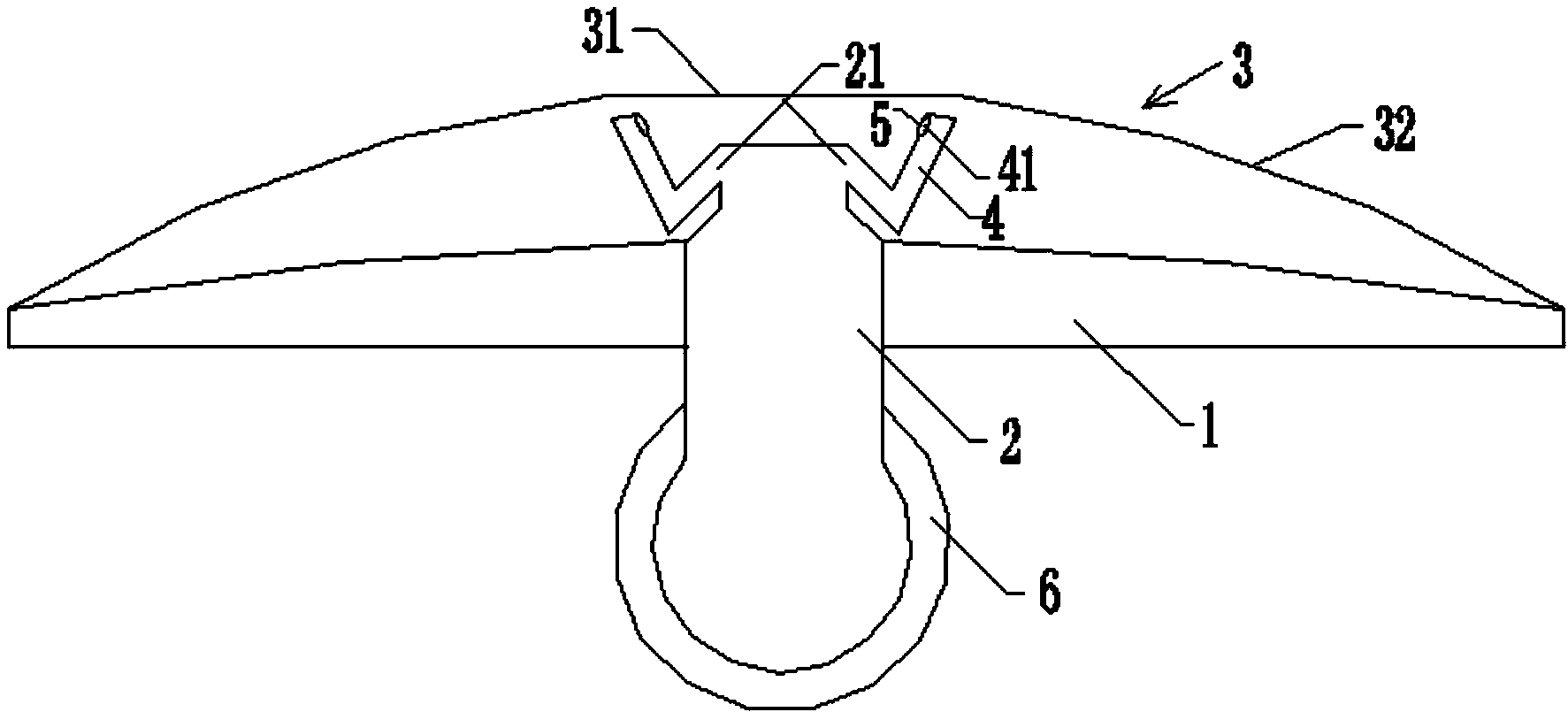
The invention discloses a disc-type micropore aerator including a flow guide disc, a rubber membrane sheet and a plurality of gas guide pipes; the middle part of the flow guide disc is provided with a hollow flow guide pipe protruding out of the upper surface of the flow guide disc, the end part of the upper end of the flow guide disc is in a sealing state, and the side wall surface of the upper end is provided with a plurality of gas guide holes; the central area of the rubber membrane sheet is a non-pore area, and the periphery area is provided with a plurality of micropores penetrating through the rubber membrane sheet; the rubber membrane sheet is positioned above the flow guide disc, the periphery edge of the rubber membrane sheet and the periphery edge of the flow guide disc are in sealing connection, and a gas guide cavity is formed between the flow guide disc and the rubber membrane sheet; the plurality of gas guide pipes are each of an V shape, one end of each of the plurality of gas guide pipes is connected with one of the plurality of gas guide holes, the side wall of the other end of each of the plurality of gas guide pipes is provided with a gas outlet hole, the gas outlet direction is that a gas flow sprays to a part of the central area of the rubber membrane sheet, and the gas outlet holes are each provided with a non-return valve. The device cannot cause pollution of ventilation pipelines.
Description
technical field [0001] The invention relates to the field of sewage treatment equipment, in particular to a disc microporous aerator. Background technique [0002] Among the many methods of sewage treatment, aerobic biological treatment is an economical and effective method. There are many factors that affect the effect of aerobic biological treatment. One of the important factors is that there must be sufficient dissolved oxygen in sewage, aeration The device is a key device for supplying oxygen to sewage. [0003] And in existing microporous aerator, the pipeline that carries out ventilation is generally designed bigger, although check valve has been arranged in the device, still have sewage to carry out to ventilation pipeline in the moment that check valve is closed, like this, along with The accumulation of sewage in the ventilation pipe will cause the pollution of the ventilation pipe. Contents of the invention [0004] The present invention aims to overcome the te...
Claims
Login to View More Application Information
Patent Timeline
 IPC IPC(8): C02F3/02C02F7/00
CPCY02W10/10
Inventor 林天祥蔡子才林斌铨谢章志蔡永远李远知
Owner GUANGXI NANNING ZHONGJIA ENVIRONMENTAL PROTECTIONVALVE MFG
Features
- R&D
- Intellectual Property
- Life Sciences
- Materials
- Tech Scout
- Unparalleled Data Quality
- Higher Quality Content
- 60% Fewer Hallucinations
Learn More Browse by: Latest US Patents, China's latest patents, Technical Efficacy Thesaurus, Application Domain, Technology Topic, Popular Technical Reports.
© 2025 PatSnap. All rights reserved.Legal|Privacy policy|Modern Slavery Act Transparency Statement|Sitemap|About US| Contact US: help@patsnap.com


