
A Dual Power Synthesizer

A synthesizer and dual-power technology, which is applied to transmission devices, transmission parts, gear transmissions, etc., can solve problems such as difficult to control complementarity and effective use, superimposed use of two forces, system hazards, etc., to achieve light weight, Large carrying capacity, the effect of large carrying capacity

Inactive Publication Date: 2017-07-25
吴速
View PDF6 Cites 0 Cited by
  • Summary
  • Abstract
  • Description
  • Claims
  • Application Information

AI Technical Summary

Problems solved by technology

However, when the two input shafts are running at the same time, and the speeds are not synchronized or the speeds of the power input shafts change randomly, it is difficult to control the two powers to complement each other and make effective use of them, and it is even more difficult to randomize the mechanical energy of the two input shafts. synthesized to the power take-off shaft
Because from the perspective of mechanical transmission, when two power shafts act on the same output shaft at the same time, the one with the lower speed will become the resistance of the one with the higher speed. Not only can the two forces not be superimposed, but it may also cause harm to the system. In order to avoid this hazard, a ratchet structure is often used on the drive shaft, but the ratchet structure cannot synthesize the two dynamic moments.
How to synthesize the output of two randomly variable mechanical power shaft speeds or torques without affecting each other, without affecting the transmission efficiency, and without adverse effects on the output shaft, there is no ideal technical solution yet.

Method used


Image

  • A Dual Power Synthesizer
  • A Dual Power Synthesizer

Examples


Embodiment Construction

[0025] The principles and features of the present invention are described below in conjunction with the accompanying drawings, and the examples given are only used to explain the present invention, and are not intended to limit the scope of the present invention.

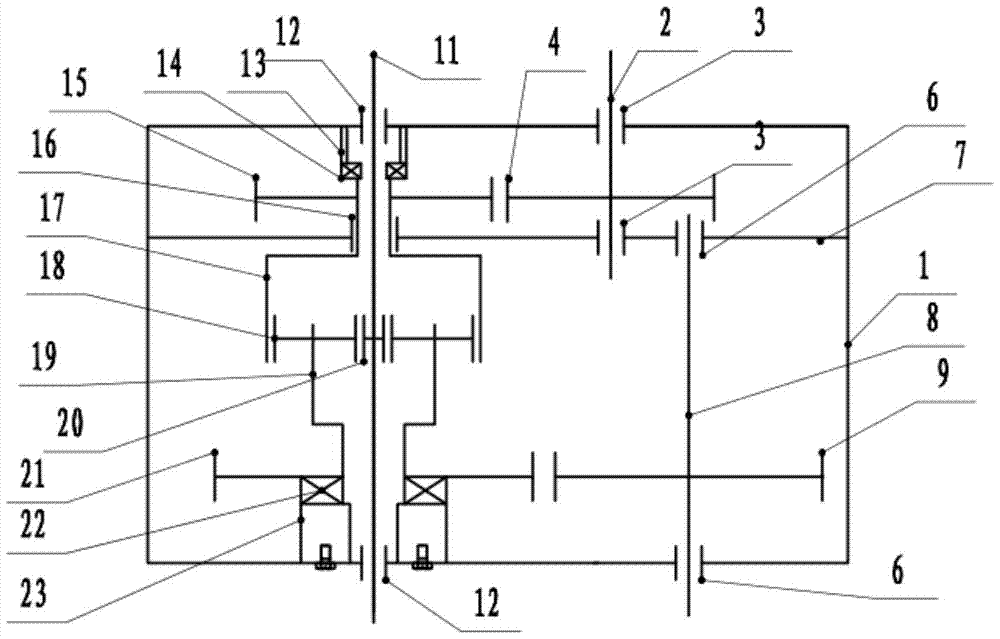
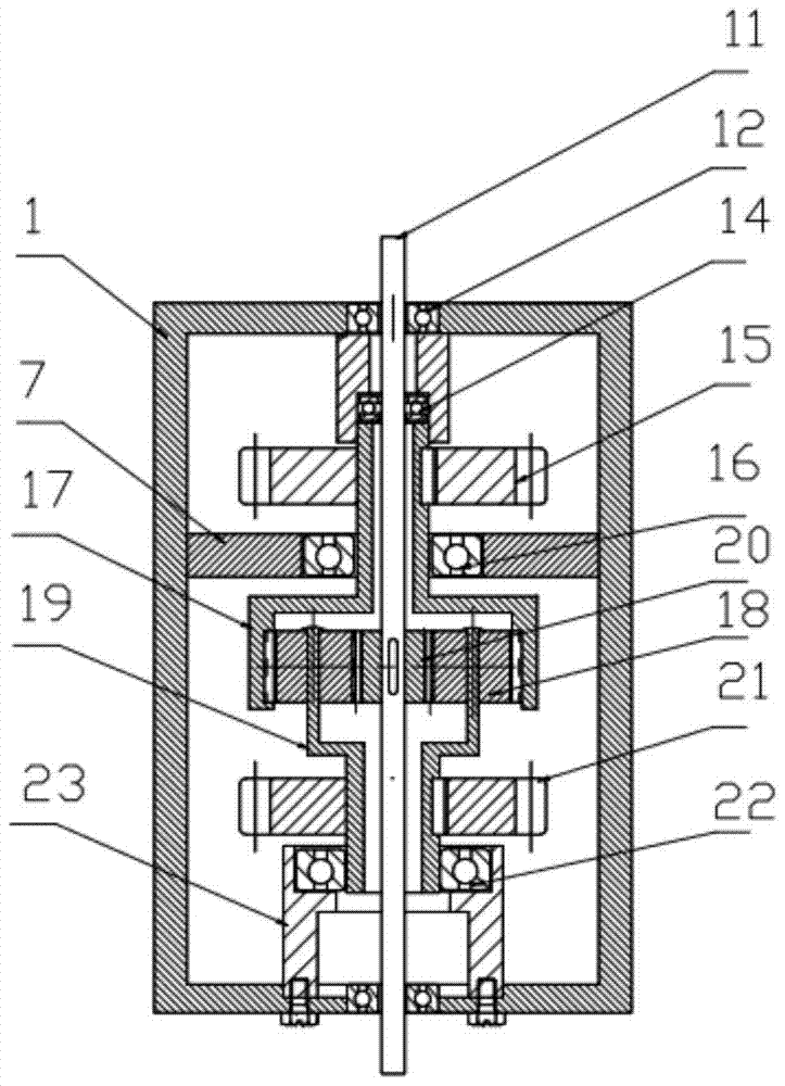
[0026] Such as Figure 1 to Figure 2 Shown, a kind of double power combiner, it comprises housing 1, and the first input shaft 2, the second input shaft 8 and the power output shaft 11 are provided with in parallel in described housing 1, and described first input shaft 2. The second input shaft 8 and the power output shaft 11 are respectively fixed on the housing 1 through the first input shaft bearing 3, the second input shaft bearing 6 and the power output shaft bearing 12, and on the first input shaft 2 A first input shaft gear 4 is provided, a second input shaft gear 9 is provided on the second input shaft 8, a planetary gear transmission system is set on the power output shaft 11, and the planetary gear transm...


PUM


Abstract

The invention relates to a dual power combiner. It includes a housing, in which a first input shaft, a second input shaft and a power output shaft are arranged parallel to each other, and the first input shaft, the second input shaft and the power output shaft pass through the first input shaft bearing respectively , the second input shaft bearing and the power output shaft bearing are fixed on the housing, the first input shaft is provided with a first input shaft gear, and the second input shaft is provided with a second input shaft gear, so A planetary gear transmission system is sleeved on the power output shaft, and the planetary gear transmission system includes a ring gear, the first input shaft gear meshes with the ring gear, and the second input shaft gear meshes with the planetary gear The frame gear is meshed, and at least one end of the first input shaft, the second input shaft and the power output shaft protrudes out of the housing for connection with external power or load. Its advantage is that it can synthesize two randomly changing input powers into one power output shaft.

Description

technical field [0001] The invention relates to the technical field of mechanical power transmission, in particular to a double power combiner. Background technique [0002] In many power drive systems, it is necessary to have two mechanical input shafts acting simultaneously or complementary, and the system shares a single output shaft. For example, the electric drive and engine drive complementary device of the car, the motor drive and pedal drive device of the electric power-assisted bicycle, the complementary drive system using wind mechanical energy and drive motor mechanical energy, etc., these can also be called dual power systems. The existing dual power system usually includes two power input shafts, a speed change device and a power output shaft. Merge switches the connection of the two input shafts to the variator. However, when the two input shafts are running at the same time, and the speeds are not synchronized or the speeds of the power input shafts change r...

Claims


Application Information

Patent Timeline
Patent Type & Authority Patents(China)
IPC IPC(8): F16H37/06
CPCF16H3/72F16H57/023
Inventor 麻常选吴速于佩民
Owner 吴速
Learn More