Star sensor demarcation method based on region division

A technology of star sensor and calibration method, which is applied to instruments, image analysis, image data processing, etc., can solve problems such as low calibration accuracy and inability to correct error sources, achieve strong versatility, improve work efficiency, and reduce calibration and testing work. amount of effect

Active Publication Date: 2014-11-26
BEIJING INST OF CONTROL ENG
View PDF5 Cites 8 Cited by
  • Summary
  • Abstract
  • Description
  • Claims
  • Application Information

AI Technical Summary

Problems solved by technology

The system error correction method currently used - the undetermined coefficient method, can correct some of the most important, large-value, and regular error sources in the star sensor system error; but it cannot correct certain error sources with relatively small values ​​and bands Some error sources with randomness are corrected, and in this method, when the field of view of the star sensor is large, it is difficult to fully approach the image plane in the full field of view by fitting a curved surface, resulting in low calibration accuracy, and The calibration residual is related to the distance from the calibration point to the center of the field of view

Method used


Image

  • Star sensor demarcation method based on region division
  • Star sensor demarcation method based on region division
  • Star sensor demarcation method based on region division

Examples


Embodiment Construction

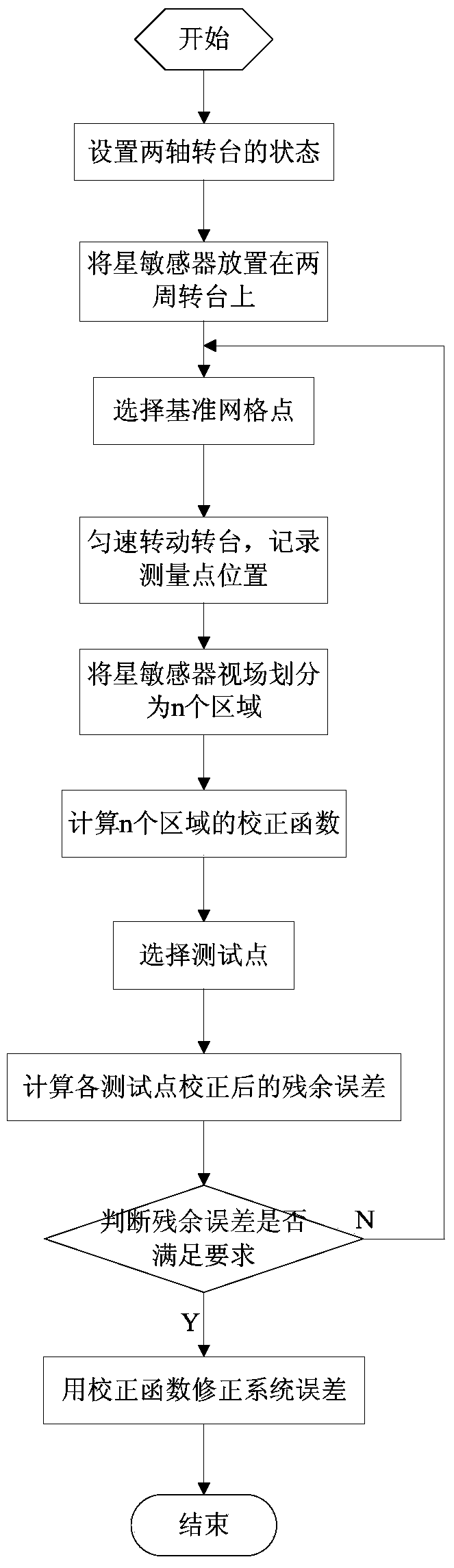
[0035] Below in conjunction with the accompanying drawings and taking the calibration test of a certain star sensor as a specific example, the working principle and merits and demerits of the present invention will be further described in detail. Such as figure 1 Shown, concrete steps of the present invention are as follows:

[0036] (1) Place the star sensor on a two-axis turntable to perform imaging observations on the single-star simulator. Record the position of the simulated star point on the image plane of the star sensor and the two-axis angular coordinates of the turntable to obtain the data of a point;

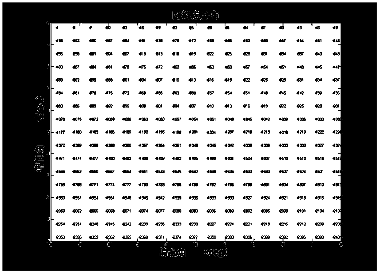
[0037] (2) Rotate the turntable again, record the position of the simulated star point on the image plane and the angular coordinates of the two axes of the turntable, and obtain another point data, and so on, measure with approximately uniform angular spacing and use it as a reference grid point;

[0038] In this test example, 289 points were selected as the refer...


PUM


Abstract

The invention discloses a star sensor demarcation method based on region division, comprising steps of (1) placing a star sensor on a two-shaft rotation table and performing imaging observation on a single-star simulator, (2) rotating the rotation table, performing measurement using the approximately uniform angle and choosing a standard grid point, (3) dividing the star sensor vision filed into n mutually independent correction areas according to the grid points, and generating a set of correction functions for each correction area, (4) choosing test points within the range not beyond the distribution boundary of the grid points, and (5) calculating the residual errors of all test points after demarcation. The invention can obtain high demarcation accuracy and is applicable to demarcation test and data processing of a large vision field optical sensor.

Description

technical field [0001] The invention relates to a star sensor calibration method, which belongs to the technical field of star sensor calibration. Background technique [0002] As an independent high-precision attitude measurement instrument, the star sensor has become an essential attitude-sensitive component on satellites, space shuttles and space stations. With the development of high-precision and high-reliability satellites, the requirements for the attitude determination accuracy of star sensors are getting higher and higher, and the systematic error of star sensors is the main factor affecting the attitude determination accuracy of star sensors. Improving the error correction level of the star sensor system is an important means to improve the measurement accuracy of the star sensor. The system error correction method currently used - the undetermined coefficient method, can correct some of the most important, large-value, and regular error sources in the star sensor...

Claims


Application Information

Patent Timeline
Patent Type & Authority Applications(China)
IPC IPC(8): G06T7/00G01C25/00
Inventor 程会艳郑然武延鹏钟俊孙大开周建涛
Owner BEIJING INST OF CONTROL ENG
Why Eureka
Try Eureka