Bus fixed contact grounding device for KYN28 type switch cabinet

A technology of grounding device and static contact, which is applied in the direction of switchgear, electrical connection seat, clip connection conductor connection, etc. It can solve the problems of personal safety hazards, equipment damage, and the inability to ensure the safety of bus power failure, so as to improve safety. and efficiency, protection of life safety, fast and convenient connection effect

Active Publication Date: 2014-11-26
JIYUAN POWER SUPPLY COMPANY OF STATE GRID HENAN ELECTRIC POWER
View PDF3 Cites 8 Cited by
  • Summary
  • Abstract
  • Description
  • Claims
  • Application Information

AI Technical Summary

Problems solved by technology

[0007] Commonly used grounding clamps are divided into crimping type and hooking type. When these types of grounding clamps clamp the conductor, the clamp can only be clamped firmly when it is perpendicular to the conductor, and cannot easily enter the static contact insulation box, even if it can Entering the static contact insulation box, the wire clip is only placed in the static contact insulation box, and it has a certain contact area with the bus static contact, which is

Method used


Image

  • Bus fixed contact grounding device for KYN28 type switch cabinet
  • Bus fixed contact grounding device for KYN28 type switch cabinet

Examples


Embodiment 1

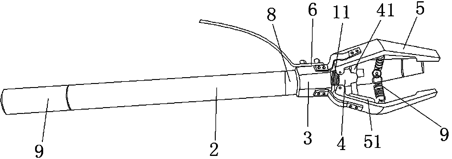
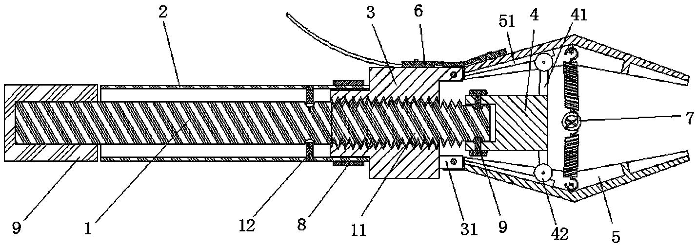
[0026] Figure 1 and figure 2 As shown, a KYN28 type switchgear busbar static contact grounding device includes an insulating material operating rod 1, an insulating material operating rod sleeve 2, a metal base 3, a push rod 4, and three metal claws 5. The lead wire 6 and the tightening device 7, the joystick 1 is cylindrical, the head of the joystick 1 is provided with a screw 11, the outer wall of the upper part of the base 3 is a regular hexagon, and the outer wall of the lower part is a cylinder Three claw seats 31 are evenly arranged around the axis of the base 3 on the edge of the upper top surface of the outer wall, and the claw seats 31 are arranged in a ring around the axis of the through hole. The inner wall of the hole is provided with a wire, the screw 11 on the top of the operating rod 1 matches the wire inside the base 3, the operating rod 1 moves up and down inside the base 3 through rotation, and the outer part of the operating rod 1 is covered with an operati...

Embodiment 2

[0028] Other technical features of the equipment in this implementation are the same as those in Example 1, except that the connection between the screw rod and the ejector rod is changed to the following structure: the bottom of the ejector rod is provided with a hollow annular base, and the inner wall of the ejector rod is connected to the wire Bearings are arranged between the outer walls of the rods, thereby reducing the steps of digging and screw holes, and the stability of the bearings is also higher, which can prolong the service life of the equipment.


PUM


Abstract

The invention belongs to the field of electrical equipment auxiliary tools and particularly relates to a bus fixed contact grounding device for a KYN28 type switch cabinet. The bus fixed contact grounding device comprises an insulating operation rod, an insulating operation rod sleeve, a metal base, an ejector rod, three metal claw pieces, a lead and stringing devices. The head of a cylindrical operation rod is provided with a lead screw. Through holes are formed in the base from top to bottom, and the inner wall is provided with threads. The upper portion of the base is provided with three claw bases. The lead screw is matched with the threads in the base. The operation rod sleeve is installed outside the operation rod in a sleeved mode. The top of the operation rod sleeve is connected with an outer wall of the base. The bottom of the operation rod extends out of the bottom of the operation rod sleeve. The claw bases are movably connected with the claw pieces. The inner walls of the claw pieces are provided with the stringing devices and used for pulling the claw pieces to the axis of the base. The uppermost end of the lead screw protrudes out of the upper top face of the base. The top end of the lead screw is provided with the ejector rod. The head of the ejector rod makes contact with the claw pieces to eject the claw pieces open. The base is provided with the lead. The device is stable in clamping, large in area making contact with a fixed contact, and fast and safe to assemble and disassemble.

Description

technical field [0001] The invention belongs to the field of auxiliary tools for electric equipment, and in particular relates to a grounding device for a static contact of a bus applied to a KYN28 switch cabinet. Background technique [0002] The KNY28 switchgear is a high-voltage switchgear, which is widely used in the power system. Electric workers must regularly perform power-off maintenance for the switchgear. During the equipment power-off maintenance, in order to ensure the personal safety of the maintenance personnel, commonly used grounding devices As a security measure, perform the following operations: [0003] 1. Use a 10kV electroscope to verify that the equipment is out of power; [0004] 2. Connect the grounding terminal of the grounding device to the grounding body to ensure its firmness and reliability; [0005] 3. The operator clamps (clamps) the grounding wire to the conductor of the power-off equipment through the insulating operating rod and ensures th...

Claims


Application Information

Patent Timeline
IPC IPC(8): H01R11/22H01R43/027H02B3/00
Inventor 张化平张亚栋张本张忠良周战胜赵永平史忠平李冬霞
Owner JIYUAN POWER SUPPLY COMPANY OF STATE GRID HENAN ELECTRIC POWER
Why Eureka
Try Eureka