A device for installing bearings of motor of washing machine

A technology of motor bearings and washing machines, which is applied in the direction of electromechanical devices, manufacturing motor generators, casings/covers/supports, etc., can solve problems such as instability, affecting motor quality, and small motor size, and achieve force balance and installation Good effect, good force transmission effect

Inactive Publication Date: 2014-11-26
HUZHOU CHARI MACHINERY & ELETRICAL SCI
View PDF0 Cites 4 Cited by
  • Summary
  • Abstract
  • Description
  • Claims
  • Application Information

AI Technical Summary

Problems solved by technology

[0002]In the prior art, the general motor, including the installation of the bearing on the motor of the washing machine, is installed manually through the installation tool of the bearing, such as the bearing installation kit, etc. Therefore, there are many problems in the efficiency problem, and because of manual installation, the application of force is often unstable, and long-term use will affect the quality of the motor. For washing machine motors, on the one hand, the size of the motor is small, and on the other hand, it needs Bearings need to be installed on the shafts at both ends of the motor stator, so a more efficient and stable installation device is required

Method used


Image

  • A device for installing bearings of motor of washing machine
  • A device for installing bearings of motor of washing machine

Examples


Embodiment 1

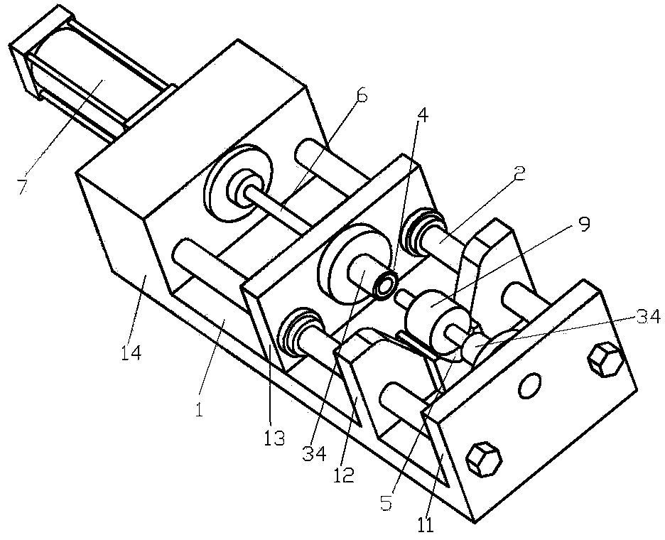
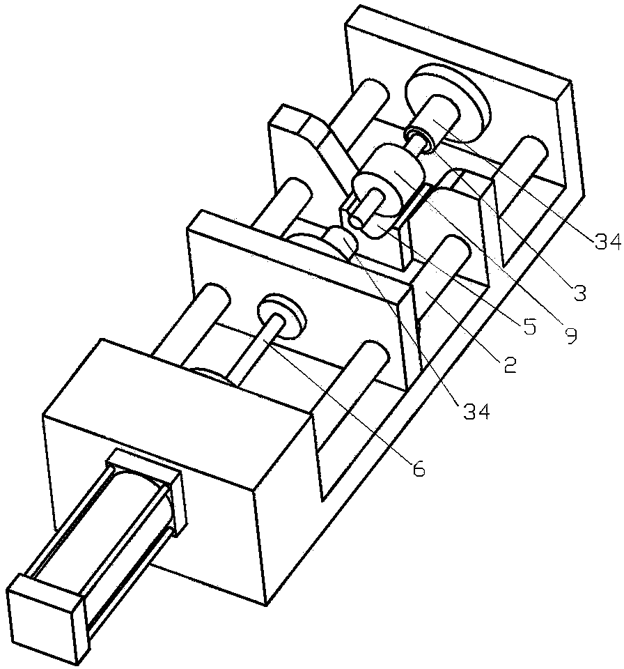
[0018] Example 1, such as figure 1 , 2 As shown, a device for installing the bearings of washing machine motors includes a bottom plate 1. The bottom plate 1 is provided with a head plate 11, a positioning plate 12 and a tail plate 14 arranged in parallel in sequence from the beginning to the end, and through two parallel and perpendicular to the head The guide column 2 of plate 11, positioning plate 12 and tail plate 14 connects head plate 11, positioning plate 12 and tail plate 14 in series, and guide column 2 is positioned at the two ends of head plate 11, positioning plate 12 and tail plate 14 and with Each plate is fixedly connected, a push plate 13 is provided between the positioning plate 12 and the tail plate 14, and the push plate 13 is also connected in series with the guide column 2 and is slidably connected with it, and the head plate 11 is provided with a fixed bearing on the side facing the positioning plate 12 Shelving groove 3, the push plate 13 facing the...

Embodiment 2

[0019] The difference between Embodiment 2 and Embodiment 1 is that the power source 7 is a hydraulic cylinder.

Embodiment 3

[0020] The difference between Embodiment 3 and Embodiment 1 is that an infrared alarm sensor is arranged on the outside of the structure with pushing action in the device.


PUM


Abstract

The invention relates to the field of machinery in the motor production, and specially relates to a device for installing bearings of a motor of a washing machine. The device comprises a bottom plate. The bottom plate is sequentially provided with a head plate, a positioning plate and a tail plate which are in parallel arrangement from the head to tail, and the head plate, the positioning plate and the tail plate are connected in series through two guide rods which are parallel to each other and are vertical to the head plate, the positioning plate and the tail plate. The guide rods are arranged at the two ends of the head plate, the two ends of the positioning plate and the two ends of the tail plate respectively and are fixedly connected with each plate. A push plate is arranged between the positioning plate and the tail plate, wherein the push plate is also connected in series with the guide rods and is in slide connection with the guide rods. The head plate is provided with a static bearing laying groove at the side directly facing the positioning plate. The push plate is provided with a moving bearing laying groove at the side directly facing the positioning plate. The positioning plate is provided with a motor positioning groove running through the positioning plate along the guide rod direction. The push plate is connected with a push rod at the side back to the positioning plate, wherein the push rod passes through the tail plate and is connected to a power source. The device for installing the bearings is simple and stable in structure and high in work efficiency.

Description

technical field [0001] The invention relates to the mechanical field in the production of motors, in particular to a device for installing bearings of washing machine motors. Background technique [0002] In the prior art, general motors, including the installation of bearings on washing machine motors, are installed manually through bearing installation tools, such as bearing installation kits, etc., so there are many problems in terms of efficiency, and because of manual installation, the force The application is often unstable, and long-term use will affect the quality of the motor. For washing machine motors, on the one hand, the size of the motor is small, and on the other hand, it is necessary to install bearings on the shafts at both ends of the motor stator, so it is necessary A more efficient and stable installation. Contents of the invention [0003] The object of the present invention is to provide a device for installing bearings of washing machine motors with...

Claims


Application Information

Patent Timeline
Patent Type & Authority Applications(China)
IPC IPC(8): H02K5/16H02K15/00
Inventor 宁慧敏
Owner HUZHOU CHARI MACHINERY & ELETRICAL SCI
Why Eureka
Try Eureka