Self-Locking Booster Compliant End Gripper with Leaf Spring

A leaf spring and gripper technology, which is applied in the field of self-locking force-enhancing flexible end grippers, can solve the problems of insufficient driving force, enlarged leaf springs, and difficult bending of leaf springs, and achieves good versatility and reliability. The effect of grasping and reducing the cross-sectional area of ​​the leaf spring

Active Publication Date: 2016-08-10
泰州市华驰不锈钢制品有限公司
View PDF6 Cites 0 Cited by
  • Summary
  • Abstract
  • Description
  • Claims
  • Application Information

AI Technical Summary

Problems solved by technology

Before the present invention, the authorized patent (Pneumatic Flexible Bending Joint with Plate Spring Framework, ZL200410065130.X) proposed a flexible bending joint with a rubber bellows expansion-loaded pneumatic artificial muscle driver and a plate spring framework. The disadvantages are: ①The internal cavity pressure of the rubber bellows pneumatic artificial muscle driver is not large enough, and the driving force is not large enough; ②Relying on the action of the leaf spring, it returns to the initial straight state; ③As the deformation of the leaf spring increases, the unit increment of the deformation The greater the pressure increase in the inner cavity of the artificial muscle, the more difficult it is for the leaf spring to bend, that is, the bending angle of the flexible finger - the slope of the air pressure curve becomes smaller and smaller; ④ Especially driven by the artificial muscle, the tension of the leaf spring is The stress increases with the increase of the pressure in the inner cavity of the artificial muscle. It is necessary to increase the cross-sectional area of ​​the leaf spring to meet the strength requirements. However, increasing the cross-sectional area of ​​the leaf spring will also increase the difficulty of large deformation of the leaf spring and reduce the flexibility of the joint. output gripping force

Method used


Image

  • Self-Locking Booster Compliant End Gripper with Leaf Spring
  • Self-Locking Booster Compliant End Gripper with Leaf Spring
  • Self-Locking Booster Compliant End Gripper with Leaf Spring

Examples


Embodiment Construction

[0025] The following is the working principle and working process of the present invention:

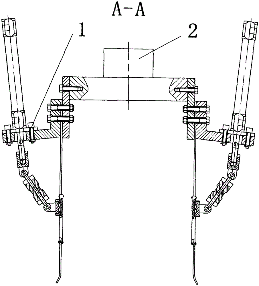
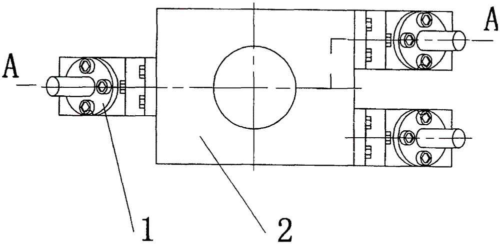
[0026] Such as figure 1 , 2 Shown, the research and analysis process: for long and rectangular complex objects, after theoretical analysis and experimental research, according to the shape, size and material conditions of the object to be grabbed, the safety range of grabbing contact force is determined, and the design is optimized The size of the structure, the characteristic parameters of the two leaf springs and the preload angle are used to determine the size of the palm and adjust the length of the two-force rod (composed of the left-threaded hinge rod 9a, the threaded sleeve 10a, and the right-threaded hinge rod 11a).

[0027] The optimization goal is: when the required gripping contact force is reached, the air pressure in the inner guide cylinder 1a reaches the system pressure, and the final included angle exceeds the friction angle of the linear guide slider 6a on the linear guide ...


PUM


Abstract

The invention relates to a self-locking power-increasing type compliant end gripper of a plate spring. The end gripper consists of a palm and three flexible fingers. The palm has two structures: rectangular and hexagonal; each flexible finger has the same structure, mainly It consists of an inner guide cylinder, a linear guide rail (or linear bearing) and two leaf springs. The leaf springs used as the skeleton are respectively deformed leaf springs and grasping leaf springs, which are driven by the cylinder to generate gripping force. This end gripper is used to grasp fragile and brittle objects, or special-shaped objects with changing shapes and sizes, and belongs to the application technology field of robots and mechatronics; it is connected with the robot body, especially suitable for food, agricultural products, and light industry. Production and logistics fields such as picking, sorting and packaging of products.

Description

Technical field: [0001] The present invention relates to a self-locking force-increasing compliant end gripper of a leaf spring. The end gripper is composed of a palm and three flexible fingers. The palm has two structures: rectangular and hexagonal; each flexible finger has the same structure, mainly It is composed of an inner guiding cylinder, a linear guide rail (or a linear bearing) and two leaf springs. The leaf springs as the framework are deformed leaf springs and grabbing leaf springs, which are driven by the cylinder to generate gripping force. This end gripper is used for the gripping of fragile and fragile objects, or special-shaped objects with varying shapes and sizes. It belongs to the application technology field of robots and mechatronics; it is connected with the robot body, especially suitable for food, agricultural products, and light industry. Production and logistics areas such as product handling, sorting and packaging. Background technique: [0002] In vie...

Claims


Application Information

Patent Timeline
Patent Type & Authority Patents(China)
IPC IPC(8): B25J15/12
Inventor 章军王芳朱飞成张秋菊
Owner 泰州市华驰不锈钢制品有限公司
Why Eureka
Try Eureka