Laser-positioning automatic robot

A laser positioning and robotic technology, applied in manipulators, manufacturing tools, etc., can solve the problems of complex mirror vibration frequency and short service life

Active Publication Date: 2014-12-03
SUZHOU CLEVA PRECISION MACHINERY & TECH
View PDF9 Cites 7 Cited by
  • Summary
  • Abstract
  • Description
  • Claims
  • Application Information

AI Technical Summary

Problems solved by technology

However, in the implementation process, the mechanical linkage structure is relatively complicated, and it is not easy for the mirror to generate high vibration frequency, and the service life of the mechanical linkage mechanism is relatively short when it works at high frequency

Method used


Image

  • Laser-positioning automatic robot
  • Laser-positioning automatic robot
  • Laser-positioning automatic robot

Examples


Embodiment Construction

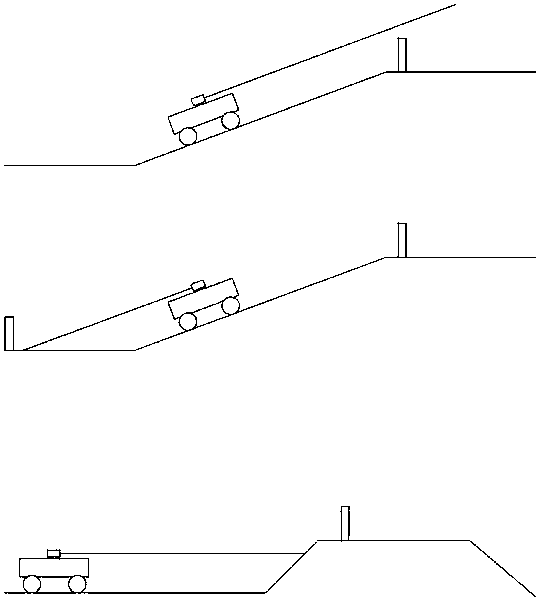
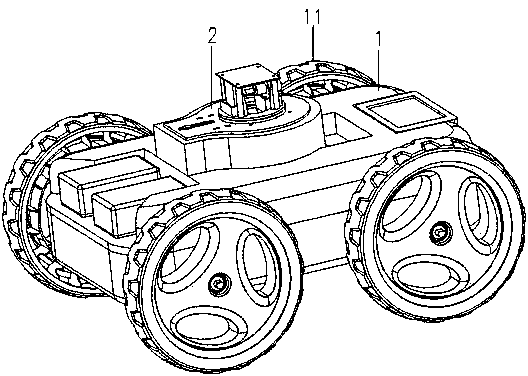
[0023] refer to figure 2 The shown robot includes a body 1 , a laser scanning mechanism 2 , and traveling wheels 11 . The body 1 is used to carry the laser scanning mechanism 2 . The laser scanning mechanism 2 is installed at a higher position of the body 1 to prevent other parts on the body from blocking the scanning laser, and the scanning laser formed by the scanning mechanism 2 continuously rotating 360° when the robot walks.

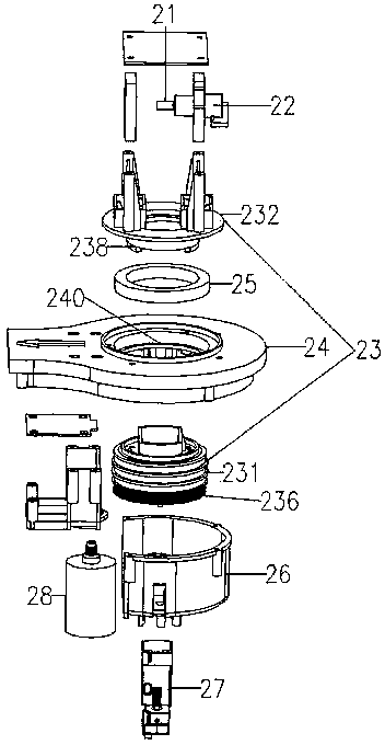
[0024] refer to image 3 The laser scanning mechanism 2 shown includes: a reflector 21, a first power motor 22, a rotating part 23, a stationary part 24, a rotating bearing 25, a bracket 26, a laser transceiver 27 integrating a transmitting part and a receiving part, and a second power motor 28. The reflective mirror 21 is thin sheet-shaped and its thickness is less than 1 millimeter. The reflective mirror 21 is arranged on the shaft of the first power motor 22, and the rotating bearing 25 is sleeved outside the rotating part 23, and the rotatin...


PUM


Abstract

The invention discloses a laser-positioning automatic robot. The laser-positioning automatic robot comprises a robot body and a laser scanning mechanism, wherein the laser scanning mechanism comprises a laser transmitting part, a laser receiving part, a reflector, a first power motor and a second power motor; the second power motor is used for driving a rotating part to rotate; the reflector is arranged on a rotating shaft of the first power motor; the first power motor is arranged on the rotating part; the first power motor drives the reflector to form swing laser; meanwhile, the first power motor rotates along with the rotating part to form scanning laser; the scanning laser can form a continuous inclined grating scanning track with certain height around the automatic robot; the track is formed by connecting densely-arrayed oblique lines; when the working area of the robot is positioned on a non-horizontal plane, the inclined grating scanning track extends in the vertical direction, and the scanning laser can be projected on a reflecting element.

Description

technical field [0001] The invention relates to a laser positioning automatic robot. Background technique [0002] In the robot navigation and positioning system, several reflective pieces are usually pre-placed in the working area of ​​the robot. The coordinates of the reflective pieces in the working area of ​​the robot are known. A laser transmitter and a laser receiver are set in the body of the robot. A rotating scanning laser is emitted horizontally to the outside at a certain angular velocity 360°. When the scanning laser scans each preset reflective member, the reflective member forms a reflected laser parallel to the scanning laser. The laser receiver receives the reflected laser, and the robot has an angle sensor that can detect the angle between the scanning laser and the robot's navigation direction. The robot navigation system includes a central processing unit and a navigation algorithm preset in the memory. The central processing unit can calculate the curren...

Claims


Application Information

Patent Timeline
Patent Type & Authority Applications(China)
IPC IPC(8): B25J19/02
Inventor 宋强姜飞孔钊
Owner SUZHOU CLEVA PRECISION MACHINERY & TECH
Why Eureka
Try Eureka