
Four-free degree double-frame magnetically suspended control moment gyro

A technology for controlling torque gyroscopes and degrees of freedom. It is used in rotating gyroscopes, spacecraft guidance devices, etc., and can solve the problems of excessive number and volume of circuit boards, poor reliability, large vibration and noise, etc. The number of circuit boards and the Reduced volume and corresponding power consumption, small rotational power consumption, and small magnetic field fluctuations

Active Publication Date: 2014-12-03
BEIHANG UNIV
View PDF6 Cites 26 Cited by
  • Summary
  • Abstract
  • Description
  • Claims
  • Application Information

AI Technical Summary

Problems solved by technology

As the supporting part of the high-speed rotor, the existing double-frame control moment gyroscope is supported by mechanical bearings, which fundamentally limits the increase of the rotor speed, reduces the service life and reliability of the system, and increases the power consumption, vibration and The noise is high and the control accuracy is low. In order to make the control moment gyro output the required angular momentum, the weight and volume of the control moment gyro have to be increased
Therefore, the main disadvantages of the existing dual-frame control moment gyroscopes are large volume and weight, low control accuracy, poor reliability, and relatively short service life.
The existing maglev dual-frame control torque gyroscope adopts a five-degree-of-freedom fully active structure. Although the structure of the permanent magnet bias magnetic bearing is adopted, its power consumption is still large, and the five-degree-of-freedom dual-frame magnetic levitation control The number and volume of the torque gyro on the circuit board are obviously too large

Method used


Image

  • Four-free degree double-frame magnetically suspended control moment gyro
  • Four-free degree double-frame magnetically suspended control moment gyro
  • Four-free degree double-frame magnetically suspended control moment gyro

Examples


Embodiment Construction

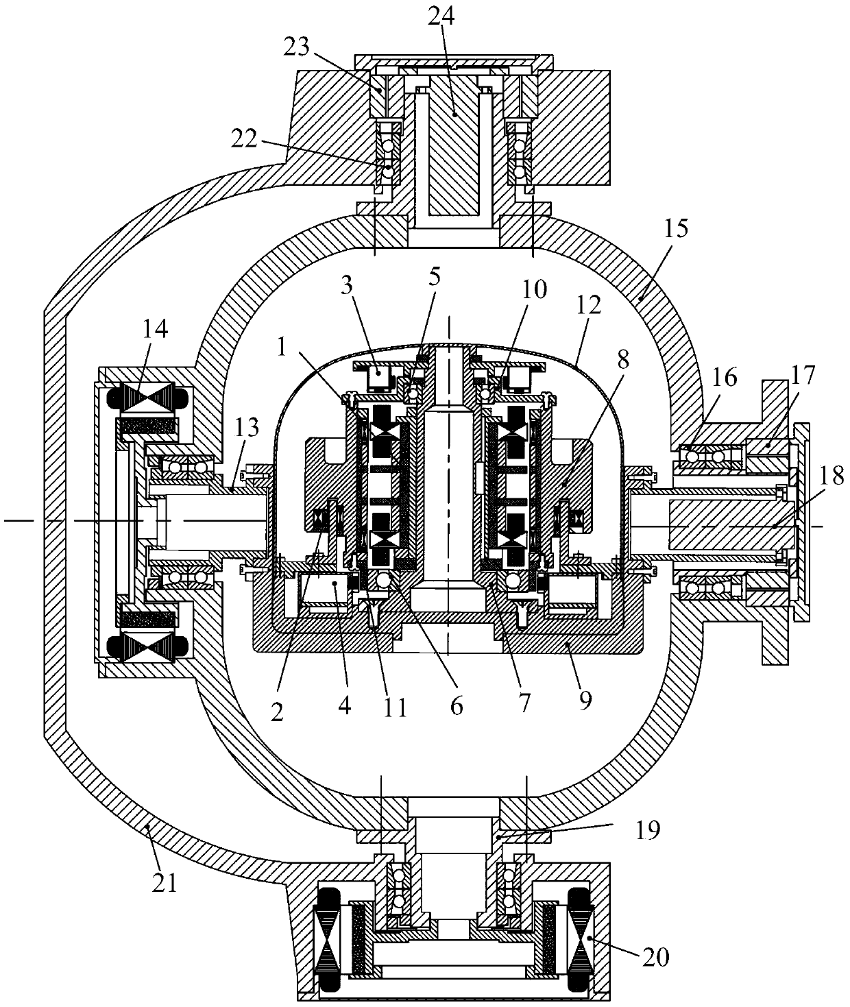
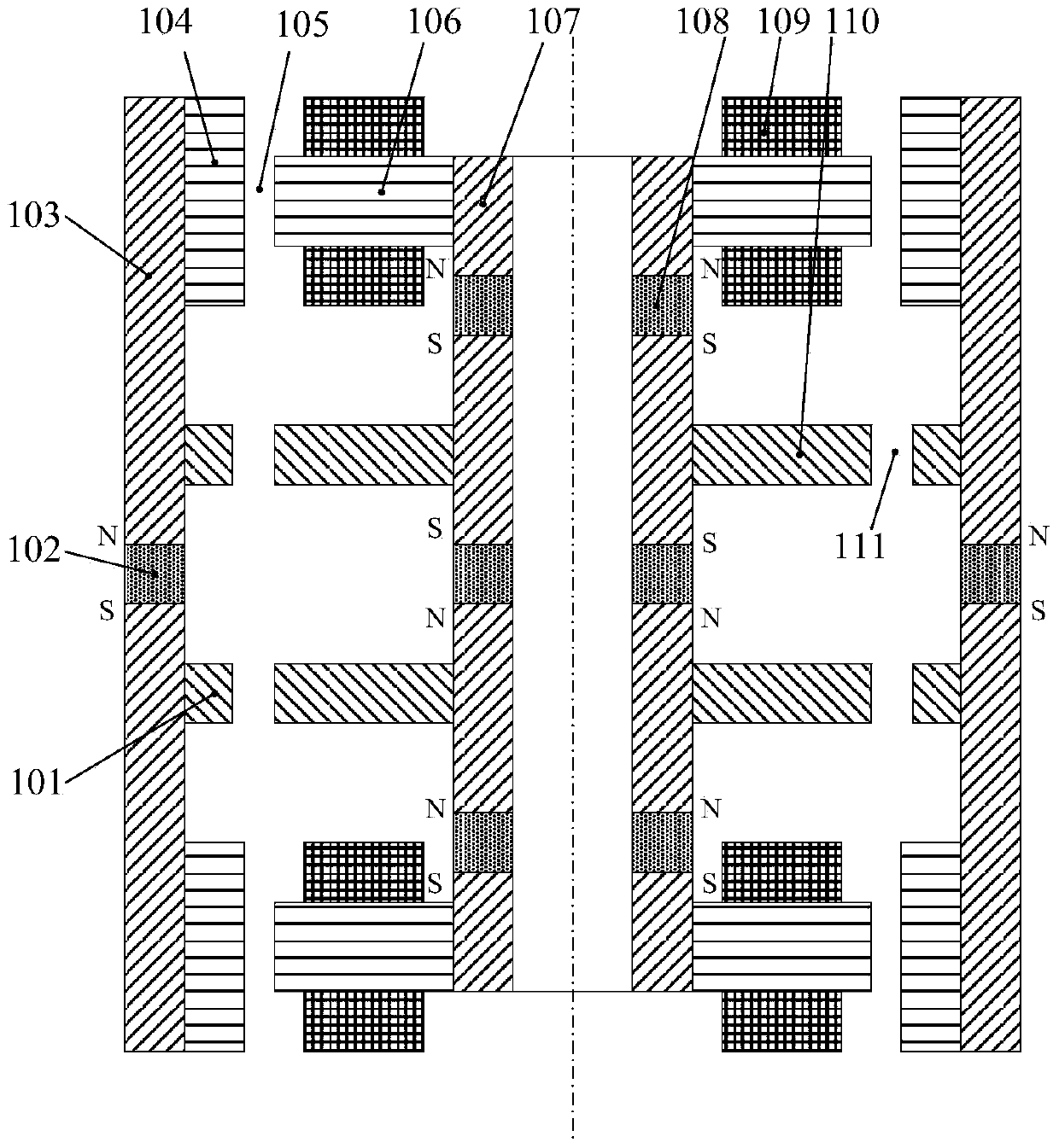
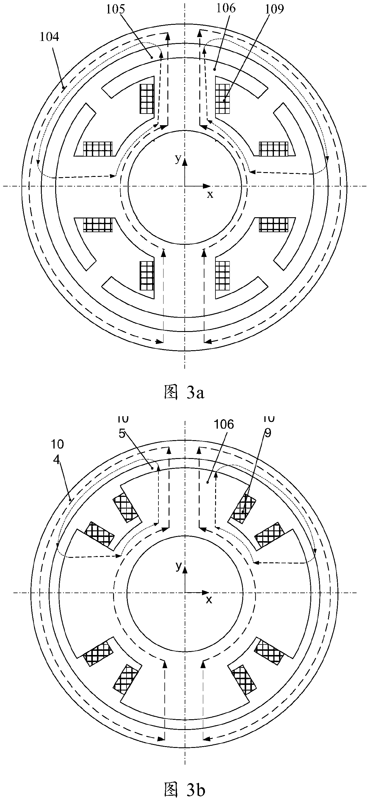
[0022] Such as figure 1 As shown, a four-degree-of-freedom double-frame magnetic levitation control moment gyroscope consists of a four-degree-of-freedom magnetic bearing (1), a high-speed motor (2), a radial-axis integrated sensor (3), a radial sensor (4), and an upper protective bearing (5), lower protective bearing (6), mandrel (7), wheel body (8), base (9), upper sensor detection ring (10), lower sensor detection ring (11), housing (12), Inner frame frame mandrel (13), inner frame frame motor (14), inner frame frame (15), inner frame mechanical bearing (16), inner frame angular position sensor (17), inner frame conductive slip ring (18), Outer frame frame mandrel (19), outer frame frame motor (20), outer frame frame (21), outer frame mechanical bearing (22), outer frame angular position sensor (23), outer frame conductive slip ring (24) , wherein the four-degree-of-freedom magnetic bearing (1) is located in the middle of the control torque gyroscope, and its stator part ...


PUM


Abstract

A four-free degree double-frame magnetically suspended control moment gyro comprises a four-free degree magnetic bearing, a high-speed motor, a diameter-axis integrated sensor, a radial sensor, an upper protection bearing, a lower protection bearing, a core shaft, a wheel body, a base, an upper sensor detection ring, a lower sensor detection ring, a housing, an inner frame core shaft, an inner frame motor, an inner frame, an inner frame mechanical bearing, an inner frame angular position sensor, an inner frame conductive slip ring, an outer frame core shaft, an outer frame motor, an outer frame, an outer frame mechanical bearing, an outer frame angular position sensor, and an outer frame conductive slip ring, wherein the driving part of the four-free degree magnetic bearing is used for controlling the radial translation and deflection of a rotor; the driven part of the four-free degree magnetic bearing is used for controlling the axial translation of the rotor. The four-free degree double-frame magnetically suspended control moment gyro has the advantages that the layout of all the components is compact; the noise, size and weight of the system are reduced; the bearing friction force is eliminated. Therefore, the service life and control precision of the four-free degree double-frame magnetically suspended control moment gyro are improved.

Description

technical field [0001] The invention relates to a double-frame magnetic levitation control moment gyroscope, which can be used as an actuator for attitude control systems of large-scale spacecraft such as spacecraft and space stations that operate for a long time or require large maneuverability and quick response. Background technique [0002] Control moment gyroscope is a kind of inertial actuator applied on large spacecraft, mainly composed of high-speed rotor and frame system, the direction of angular momentum of high-speed rotor is controlled by frame servo system, so as to output gyro torque to control the attitude of spacecraft. The attitude control actuators of spacecraft requiring large maneuverability and quick response and large spacecraft such as space stations require large output torque, long life, high reliability, fast response, high precision, small size, light weight, and low power consumption. This requires the high-speed rotor that outputs angular momentu...

Claims


Application Information

Patent Timeline
Patent Type & Authority Applications(China)
IPC IPC(8): B64G1/28G01C19/24
Inventor 孙津济汤继强刘虎韩伟涛乐韵
Owner BEIHANG UNIV
Learn More