Liquefied natural gas pump lifting device

A technology of liquefied natural gas and rotating devices, which is applied in cranes, transportation and packaging, load suspension components, etc., can solve the problems of limited rotating range, larger devices as a whole, and increased costs, so as to achieve sufficient safety and light weight , the effect of ensuring safety

Inactive Publication Date: 2014-12-03
SAN EI SEIKI SEISAKUSHO
View PDF2 Cites 3 Cited by
  • Summary
  • Abstract
  • Description
  • Claims
  • Application Information

AI Technical Summary

Problems solved by technology

[0005] However, in the above existing such as Figure 5 When the illustrated LNG pump hoisting device 1 is installed on the upper part of the LNG storage tank 6, since the rotation device 4 is located at the lower part of the support column 5, in terms of safety inspection or maintenance after installation, it is difficult to obtain the pump stand from the pump platform. 8b can be seen visually, so there is no need to climb up the pillar 5 in terms of maintenance, which is advantageous. However, in terms of the installation of the rotating device 4, because of the structure for rotating the pillar 5, it is necessary to be familiar with various wiring devices or application. For the balance of the weight of the rotating device 4, etc., the operator
[0006] Specifically, when installing the LNG pump hoisting device, since the rotating device 4, its mechanical rotating structure, a motor unit (not shown) for starting the rotating device 4, and its circuit structure (not shown) are arranged Therefore, the overall manufacturing of the LNG pump hoisting device is integrated. It is necessary to pay attention to the composition and arrangement of each component and make adjustments based on experience. In this case, not only the boom 3 and the elevators 2a, 2b, but also the weight of the pillar 5 is loaded on the rotating device 4, so that rotation energy is additionally required, and there is a problem in terms of fuel efficiency.
[0007] In addition, in Figure 4 In another LNG pump hoisting device shown in , the structure in which the boom 3 is installed on the rotating shaft arranged along the pillar 5 along the horizontal direction is formed, so that there will be no such Figure 5 Problems such as the LNG pump hoisting device shown in Figure 4 In the case of the rotating device 4, the boom 3 is rotated by the rotating shaft, and the range of rotation is limited. Therefore, when lifting multiple LNG pumps, it is necessary to pay attention to the direction of rotation of the rotating shaft, and the operation is complicated.
[0008] In addition, the demand for installation of LNG storage facilities in foreign countries is currently increasing. In this case, in the case of installing the above-mentioned lifting device, it is necessary to assemble and manufacture parts of the lifting device such as the pillar part, the boom, and the elevator in the factory. , after one assembly and fine-tuning, it is transported to the installation site, where a skilled operator needs to perform all the setting operations again, which poses a problem in terms of operational efficiency or transport cost
[0009] In addition, in the conventional LNG pump hoisting device, in order to detect the sum of the loads applied to the plurality of elevators used, mechanical overload detection using a hydraulic cylinder as shown in Patent Document 2 is used. Due to the adoption of the hydraulic cylinder, maintenance becomes complicated and the overall size of the device increases, so there are problems of increased weight and cost.

Method used


Image

  • Liquefied natural gas pump lifting device
  • Liquefied natural gas pump lifting device
  • Liquefied natural gas pump lifting device

Examples


Embodiment Construction

[0060] Hereinafter, modes for implementing the present invention will be described with reference to the drawings.

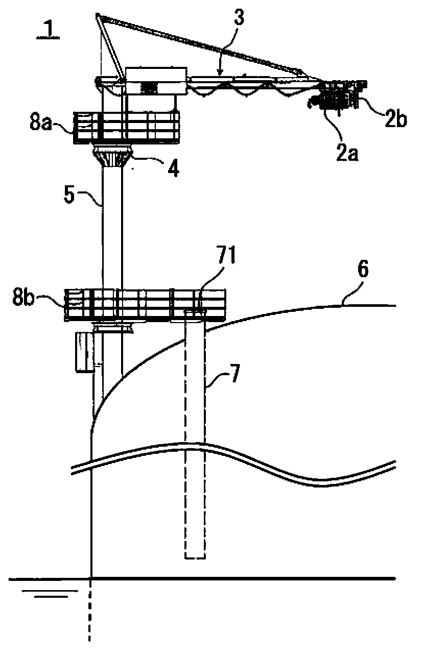
[0061] figure 1 It shows a preferred embodiment of the LNG pump lifting device 1 according to the present invention, which is arranged on the upper part or the side part of the LNG storage tank 6 installed on the ground or semi-underground, and its structure is such that the pillar 5 is vertically arranged, and above the pillar 5 The rotating device 4 is arranged, and the cantilever 3 extending from the upper end on the axis of the support 5 is installed in a direction substantially parallel to the table surface 8a provided on the upper side of the rotating device 4. The cantilever 3 is rotated by the upper part of the support 5. The device 4 is arranged rotatably at the center.

[0062] In addition, the structure is such that an elevator 2a and an elevator 2b that can move along the boom 3 are arranged, and near the front end in the center direction of the LN...


PUM


Abstract

The invention provides a liquefied natural gas pump lifting device which is simple to move and install and easy to maintain and operate. The liquefied natural gas pump lifting device comprises a supporting column which is vertically arranged on the ground or a storage tank at the side of the liquefied natural gas storage tank; a bench top arranged above the supporting column through a rotation part; a cantilever which is arranged above the bench top on one end of the upper part of the supporting column in a manner of extending in a direction roughly parallel to the bench top; and an elevator provided with a pump lifting device capable of moving along the cantilever. All parts except the supporting column can be detached/assembled. Preferably, the elevator of the liquefied natural gas pump lifting device is provided with a non-oil-pressure type overloading detection device.

Description

technical field [0001] The present invention relates to a hoisting device for an LNG pump installed in an LNG storage tank of a liquefied natural gas (hereinafter abbreviated as "LNG") storage facility. Background technique [0002] As a simple energy source, LNG is widely used in general households, various factories, and business sites, and is generally stored in storage facilities having large storage tanks and supplied. [0003] In addition, LNG is usually sucked up and discharged from the underground or above-ground storage tanks of the above-mentioned storage facilities by means of an LNG pump. The LNG pump used to suck up the above-mentioned LNG is structurally installed on the side of the storage tank due to the nature of LNG. Near the bottom, when the LNG pump is replaced for maintenance or repair, it is necessary to lift the LNG pump from the storage tank. In most cases, the storage equipment generally has a special LNG pump lifting device. [0004] Figure 4 An e...

Claims


Application Information

Patent Timeline
Patent Type & Authority Applications(China)
IPC IPC(8): B66C13/16B66C23/88
Inventor 村冈忠信佐藤真渊本龙
Owner SAN EI SEIKI SEISAKUSHO
Why Eureka
Try Eureka