
A steel ball charging device

A technology of charging device and steel ball, applied in quenching device, furnace, heat treatment equipment and other directions, can solve the problems of high labor intensity and waste of quenching liquid

Active Publication Date: 2016-08-24
宁国东方碾磨材料股份有限公司
View PDF9 Cites 0 Cited by
  • Summary
  • Abstract
  • Description
  • Claims
  • Application Information

AI Technical Summary

Problems solved by technology

In the production process of steel balls, in order to improve the mechanical properties of steel balls, heat treatment is usually carried out. After heat treatment, quenching treatment is required. After quenching, cooling is carried out for packaging. In the prior art, the above-mentioned process is mainly done manually, which has high labor intensity and The surface of the steel ball is stuck to the quenching liquid to cause waste, which needs to be improved

Method used


Image

  • A steel ball charging device
  • A steel ball charging device
  • A steel ball charging device

Examples


Embodiment Construction

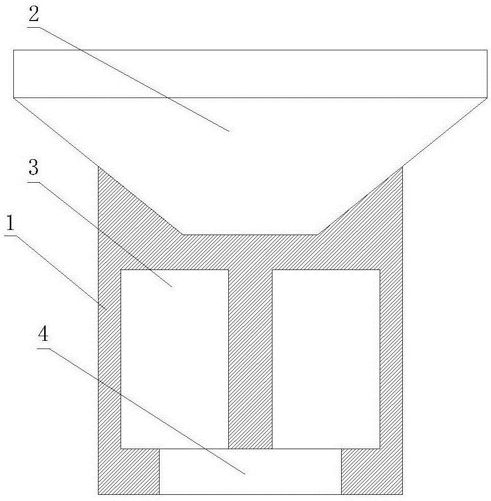
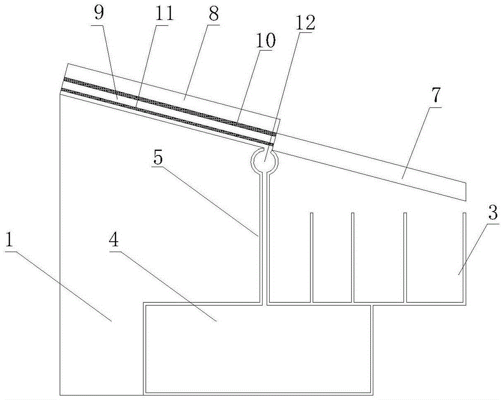
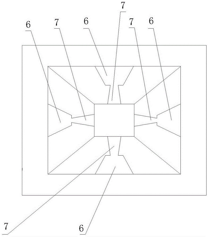
[0012] Such as Figure 1-3 as shown, figure 1 It is a structural schematic diagram of a steel ball charging device proposed by the present invention; figure 2 for figure 1 Partial sectional view of image 3 for figure 1 Schematic diagram of the local top view structure.

[0013] refer to Figure 1-3 , a steel ball charging device proposed by the present invention includes a bracket 1, a screening box 2 and a collection box 3, the screening box 2 and the collection box 3 are all installed on the bracket 1, and the screening box 2 is located above the collection box 3 The screening box 2 is funnel-shaped, and the surrounding walls of the screening box 2 are provided with multiple slideways, and the slideways extend from the screening box 2 upper end to the screening box 2 lower ends, and the distances between adjacent slideways are all equal, and the slideways It is formed by connecting the upper liquid collection channel 6 and the lower channel channel 7, wherein the bot...


PUM


Abstract

The invention discloses a steel ball charging device, which comprises a bracket, a screening box and a collecting box. The screening box is located above the collecting box; The channel extends from the upper end of the screening box to the lower end of the screening box, and the slideway is formed by connecting the upper liquid collection channel and the lower channel channel, wherein there is a gap at the bottom of the channel channel, and the connection between the liquid collecting channel and the channel channel is located Just above the side of the tank, there is a screen in the liquid collecting channel that divides the liquid collecting channel into a sliding area and a liquid collecting area. connected and the bottom of the ring groove is provided with a liquid outlet, the liquid outlet is connected with the external liquid storage device through the rubber tube, the width of the gap at the bottom of the channel gradually increases from the end close to the liquid collection channel to the end away from the liquid collection channel; the collection box is composed of A plurality of "back" shaped plates nested with each other divide the collecting box into multiple collecting areas from the outside to the inside, and the bottom of each collecting area is provided with a discharge port.

Description

technical field [0001] The invention relates to the technical field of steel ball collecting equipment, in particular to a steel ball charging device. Background technique [0002] Ball mill is one of the high-fine grinding machines widely used in industrial production. The steel ball of the ball mill is the grinding material medium of the ball mill equipment. The grinding effect is produced through the collision and friction between the steel balls of the ball mill and between the steel ball and the material. It is an important basic component, especially the precision industrial steel ball plays an important role in the development of the national economy. has a huge effect. In the production process of steel balls, in order to improve the mechanical properties of steel balls, heat treatment is usually carried out. After heat treatment, quenching treatment is required. After quenching, cooling is carried out for packaging. In the prior art, the above-mentioned process is ...

Claims


Application Information

Patent Timeline
Patent Type & Authority Patents(China)
IPC IPC(8): C21D9/36C21D1/62
Inventor 赵金斌杨霄葛兴洋
Owner 宁国东方碾磨材料股份有限公司
Learn More