Warp knitting machine with improved structure

An improved structure and warp knitting machine technology, which is applied in warp knitting, textiles, papermaking, knitting, etc., can solve the problems that warp knitted fabrics cannot be divided, and achieve the effects of high cutting efficiency, stable work and wide application range

Active Publication Date: 2014-12-03
海宁市成达经编股份有限公司
View PDF6 Cites 10 Cited by
  • Summary
  • Abstract
  • Description
  • Claims
  • Application Information

AI Technical Summary

Problems solved by technology

[0004] Although the warp knitting machine disclosed in this patent can save raw materials and improve production efficiency, the warp knitting machine cannot automatically divide the warp knitting fabric. Therefore, it is necessary to design a warp knitting machine with an improved structure

Method used


Image

  • Warp knitting machine with improved structure
  • Warp knitting machine with improved structure
  • Warp knitting machine with improved structure

Examples


Embodiment 2

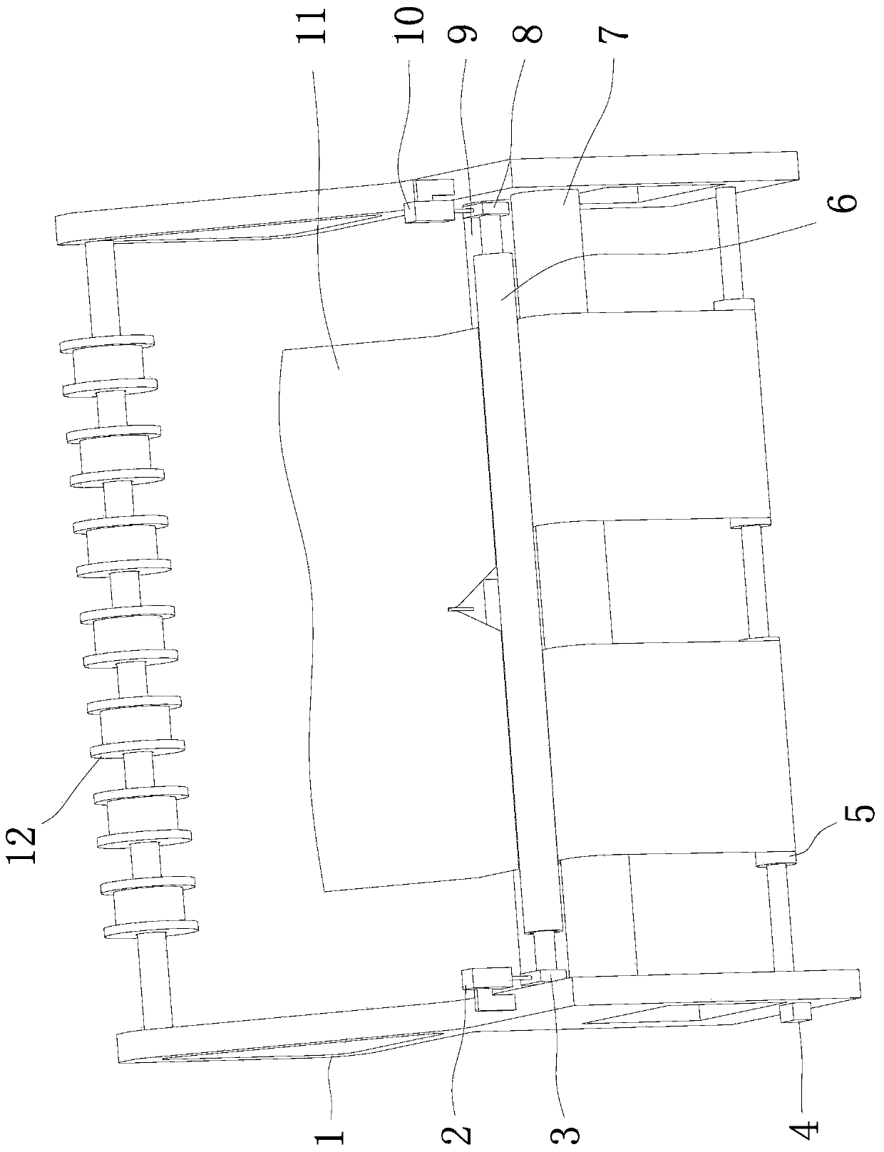
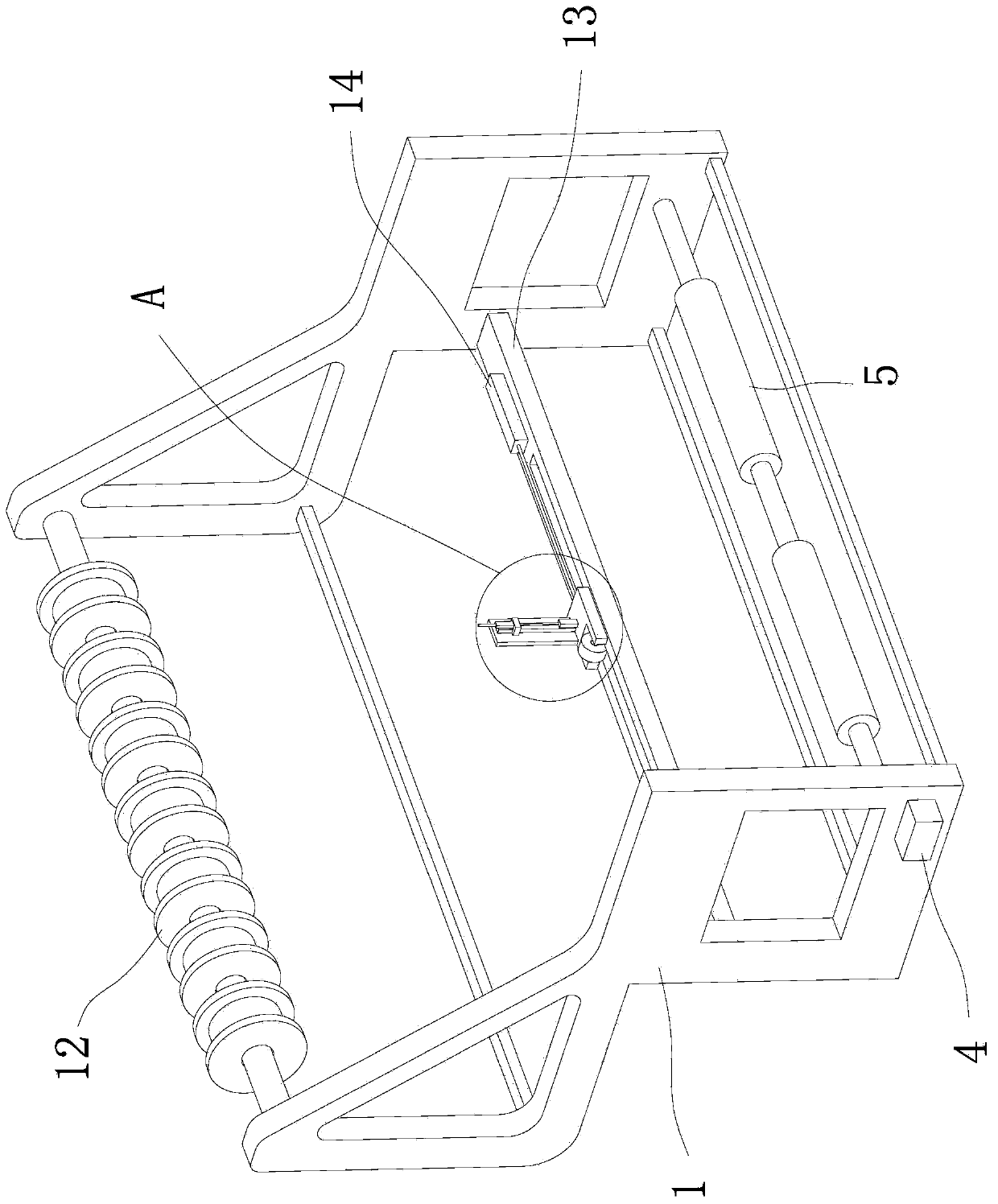
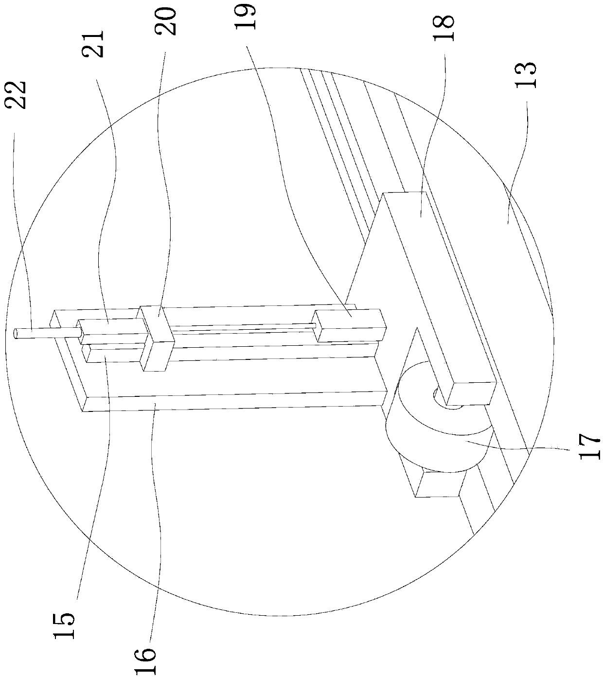
[0046] The content in the second embodiment is roughly the same as that in the first embodiment, except that the dividing device in the first embodiment includes a heating wire 22, and the upper end of the heating wire 22 is a working end that can be in contact with the warp knitted fabric 11. The lower end of the heating wire 22 links to each other with a lifting and positioning mechanism two that can drive it up and down and locate it; Between the bobbin 12 and the conveying shaft one 9, the lower end of the fixed plate 16 is connected with a moving mechanism that can drive it to move laterally. The guide rail 15 is fixed on the fixed plate 16 and arranged along the up and down direction. The slider 20 is arranged on the guide rail 15, the upper end of the insulating plate 21 is fixedly connected with the heating wire 22, the lower end of the insulating plate 21 is fixed on the slider 20, and the lower part of the slider 20 is also provided with a vertical cylinder 19 that ca...

Embodiment 3

[0048] The content in the third embodiment is roughly the same as that in the second embodiment, except that the rotating mechanism in the second embodiment includes a motor 32, a driving gear 31, a driven gear 30, an upper positioning bearing and a lower positioning bearing. The inner ring of the locating bearing is set and fixed on the uppermost end of the screw rod 33, the outer ring of the upper locating bearing is fixed on the frame 1, and the upper locating bearing is fixed on the frame 1 through the upper locating bearing seat 25; the inner ring of the lower locating bearing The snare is arranged at the lower end of the screw rod 33, the outer ring of the lower positioning bearing is fixed on the frame 1, and the lower positioning bearing is fixed on the frame 1 through the lower positioning bearing seat 24; the driven gear 30 is fixed at the lowermost end of the screw rod 33 , the motor 32 is fixed on the frame 1, the output shaft of the motor 32 is vertically upward, t...


PUM


Abstract

The invention provides a warp knitting machine with an improved structure, belongs to the technical field of machinery, and solves the technical problems that a warp knitting machine in the prior art cannot automatically cut warp knitting fabric and the like. The warp knitting machine with the improved structure comprises a rack, wherein a bobbin used for winding yarn as well as a first conveying shaft and a second conveying shaft which are used for conveying the warp knitting fabric is fixed on the rack; and the first conveying shaft and the second conveying shaft are parallel, are close and are not contacted, a pressing shaft is arranged above a gap between the first conveying shaft and the second conveying shaft and is connected with a lifting positioning mechanism I which can drive the pressing shaft to go up and down and can position the pressing shaft, the outer diameter of the pressing shaft is larger than the gap between the first conveying shaft and the second conveying shaft, and a cutting device which can cut the warp knitting fabric into two parts is arranged between the bobbin and the first conveying shaft. The warp knitting machine has the advantages of capability of automatically cutting the warp knitting fabric, high cutting efficiency and wide application range.

Description

technical field [0001] The invention belongs to the technical field of machinery, and relates to a warp knitting machine, in particular to a warp knitting machine with an improved structure. Background technique [0002] Warp-knitted fabrics are formed by knitting one or more groups of warp yarns into loops on a warp-knitting machine and interlocking each other. [0003] After retrieval, such as Chinese patent literature discloses a warp knitting machine [patent number: ZL201220453852.2; authorized announcement number: CN202898728U]. This warp knitting machine includes a transmission mechanism and a knitting mechanism, and is characterized in that: the transmission mechanism includes a motor, an equal diameter cam assembly and a swing arm assembly, and the equal diameter cam assembly includes a rotation shaft and a roller set positioned The equal-diameter cam on the slide plate, the slide plate is movably connected to the slide plate seat; the swing arm assembly includes a ...

Claims


Application Information

Patent Timeline
Patent Type & Authority Applications(China)
IPC IPC(8): D04B27/00D04B27/26
Inventor 张波
Owner 海宁市成达经编股份有限公司
Why Eureka
Try Eureka