A constant velocity drive shaft of an automobile

A constant-speed drive shaft and automobile technology, applied in the field of high-speed drive shafts and automobile transmission system drive shafts, can solve problems such as deviation

Active Publication Date: 2017-01-04
精诚工科汽车系统有限公司
View PDF7 Cites 0 Cited by
  • Summary
  • Abstract
  • Description
  • Claims
  • Application Information

AI Technical Summary

Problems solved by technology

[0004] The purpose of the present invention is to aim at the drawbacks of the prior art, and to provide a vehicle that can not only solve the problem of deviation caused by the inconsistency of the torsion angle of the left and right axle shafts when the vehicle is running under dynamic load, but also eliminate the problem caused by different engine speeds (within a wide frequency band). Resonance Phenomenon, Automotive Constant Velocity Drive Shaft for Improving Vehicle NVH Performance

Method used


Image

  • A constant velocity drive shaft of an automobile
  • A constant velocity drive shaft of an automobile
  • A constant velocity drive shaft of an automobile

Examples


Embodiment Construction

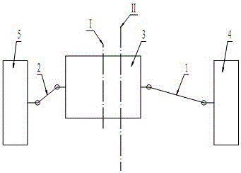
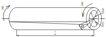
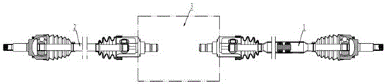
[0023] see image 3 , Figure 4 , Figure 7 , the present invention includes a left half shaft 2 and a right half shaft 1, wherein the left end of the left half shaft is assembled with the left side wheel 5 through the left half shaft fixed joint 1-3, and the right end of the left half shaft is connected with the power through the left half shaft moving joint 1-2 The left half-shaft gear of the differential in the transmission device 3 is assembled, the left end of the right half-shaft is assembled with the right half-shaft gear of the differential in the power transmission device 3 through the right half-shaft moving joint 1-2, and the right end of the right half-shaft passes through The right half shaft fixed section 1-3 is assembled with the right wheel 4, the right half shaft 1 is a hollow shaft tube structure, the left half shaft is a solid rod shaft structure, and the right half shaft hollow shaft tube 1-1 has a length of X , the length of the left half-axis solid rod ...


PUM


Abstract

A constant velocity drive shaft of an automobile, including a left half shaft and a right half shaft, wherein the left end of the left half shaft is assembled with the left wheel through the left half shaft fixed joint, and the right end of the left half shaft is connected with the middle differential of the power transmission device through the left half shaft moving joint The left half shaft gear of the transmission is assembled, the left end of the right half shaft is assembled with the right side shaft gear of the differential in the power transmission device through the right half shaft movable joint, and the right end of the right half shaft is connected with the right wheel through the right half shaft fixed joint. Assembly, the right half shaft is a hollow shaft tube structure, the left half shaft is a solid rod shaft structure, the length of the right half shaft hollow shaft tube is X, the length of the left half shaft solid rod shaft is Y, X>Y, the right half shaft The shaft torsional stiffness is K right, the left half shaft torsional stiffness is K left, and K right = K left. The invention not only solves the deviation problem caused by the inconsistency of the torsion angles of the left and right axle shafts when the whole vehicle is running under dynamic load during acceleration, but also eliminates the resonance phenomenon caused by the different speed conditions of the engine, and improves the NVH performance and economic performance of the vehicle.

Description

technical field [0001] The invention relates to a driving shaft of an automobile transmission system, in particular to an automobile constant-velocity driving shaft, belonging to the technical field of automobile transmission shafts. Background technique [0002] With the improvement of people's requirements for the driving reliability and NVH performance of automobiles, the design level of various parts of automobile chassis is continuously improved. The impact on NVH performance cannot be ignored either. [0003] as attached figure 1 As shown, in the prior art, for front-wheel-drive vehicles and SUV vehicles, since the arrangement of the engine is biased to the left side of the vehicle body, the central axis I of the power transmission device 3 does not coincide with the central axis II of the vehicle body, so it is necessary to move the drive shaft to the right Half shaft 1 is designed longer and its shaft is designed as a solid structure with an external vibration damp...

Claims


Application Information

Patent Timeline
Patent Type & Authority Patents(China)
IPC IPC(8): F16D3/22F16F15/10
Inventor 王庚川于春博杜阿雷许超楠张慧波张旭东马勇
Owner 精诚工科汽车系统有限公司
Why Eureka
Try Eureka