Rapid calibration method of robot visual system
A robot vision and vision system technology, applied in the field of robot coordinate setting, can solve the problems of many prerequisites, large amount of calculation, and inability to realize simple and quick calibration, and achieve the effect of reducing manual participation and strong practicability
- Summary
- Abstract
- Description
- Claims
- Application Information
AI Technical Summary
Problems solved by technology
Method used
Image
Examples
Embodiment 1
[0042] Example 1: See figure 1 .
[0043] At present, manipulators generally have their own stepping coordinate system, such as the stepping program of wire cutting, etc.; when the vision system is used to control other transmission devices to cooperate with the manipulator, the coordinate system of the vision system and the coordinate system of the manipulator need to be unified.
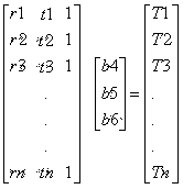
[0044] The rapid calibration method of the robot vision system is used to convert the robot coordinates to a robot vision system coordinate, which includes the following steps:
[0045] Step 1: Set up a calibration board. The calibration board is equipped with a number of preset points for the sensing of the camera device in the vision system, and a coordinate system is established for the calibration board; the coordinate system is based on the coordinate system of the manipulator device itself. The two coordinate systems are equivalent.
[0046] Step 2. The manipulator sets a sensing point for calibratin...
Embodiment 2
[0063] Example 2: see figure 2 .
[0064] The rapid calibration method of the robot vision system is used to convert one of the vision system coordinates to the other vision system coordinates, including the following steps:
[0065] Step 1: Set up a calibration board, which is equipped with multiple preset points for vision system sensing;
[0066] Step 2. Provide a manipulator. The manipulator sets a sensing point for calibrating the movement of the manipulator; set the movement rules of the manipulator according to the position of the preset point. The manipulator is controlled by the processor so that the sensing point is located at the preset point every time the manipulator moves Above:
[0067] Step 3. The manipulator starts to move, and the first camera of one vision system and the second camera of the other vision system respectively take images of the manipulator; the display windows of the two vision systems are divided into coordinates; or the coordinates of the two visio...
PUM
 Abstract
Description
Claims
Application Information
 - R&D
- Intellectual Property
- Life Sciences
- Materials
- Tech Scout
- Unparalleled Data Quality
- Higher Quality Content
- 60% Fewer Hallucinations
Browse by: Latest US Patents, China's latest patents, Technical Efficacy Thesaurus, Application Domain, Technology Topic, Popular Technical Reports.
© 2025 PatSnap. All rights reserved.Legal|Privacy policy|Modern Slavery Act Transparency Statement|Sitemap|About US| Contact US: help@patsnap.com


