
A signal compensation circuit for a water supply remote monitoring system

A remote monitoring system and signal compensation technology, applied in the circuit field, can solve problems such as signal distortion, signal frequency hopping, attenuation, etc.

Active Publication Date: 2019-05-31
ZHENGZHOU LITONG WATER CO LTD
View PDF8 Cites 14 Cited by
  • Summary
  • Abstract
  • Description
  • Claims
  • Application Information

AI Technical Summary

Problems solved by technology

[0002]In order to solve the problem of safe water supply for urban residents, many local tap water plants have built small water plants to collect groundwater or surface water and transport it to the water plant for treatment in the water plant to achieve drinking After standardization, the water is transported to the main pipeline through a booster pump, and then the water is sent to each urban household by a branch pipeline. In order to improve production efficiency and water supply management level, the water plant manager hopes to establish a remote monitoring and management system for water supply. That is, the signal compensation circuit used in the water supply remote monitoring system. However, in practical applications, the signal in the signal input terminal of the control terminal receiving signal in the water supply remote monitoring system encounters complex environments during transmission, such as humid and strong magnetic environments. In this case, the signal often appears frequency hopping and attenuation, which makes the signal distorted

Method used


Image

  • A signal compensation circuit for a water supply remote monitoring system
  • A signal compensation circuit for a water supply remote monitoring system
  • A signal compensation circuit for a water supply remote monitoring system

Examples


Embodiment 1

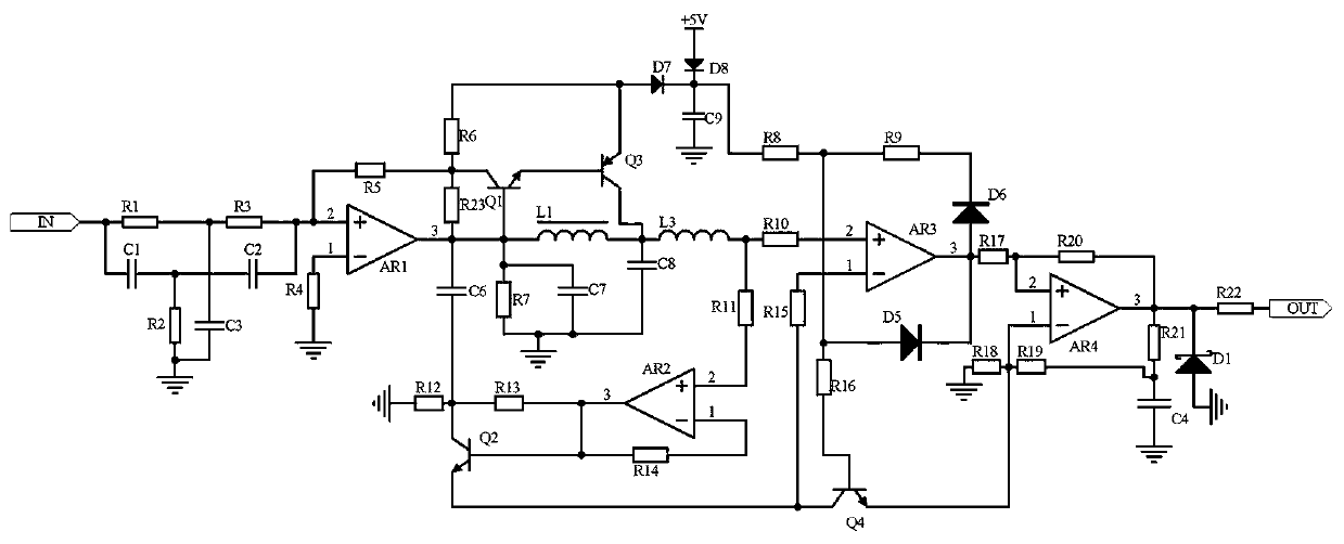
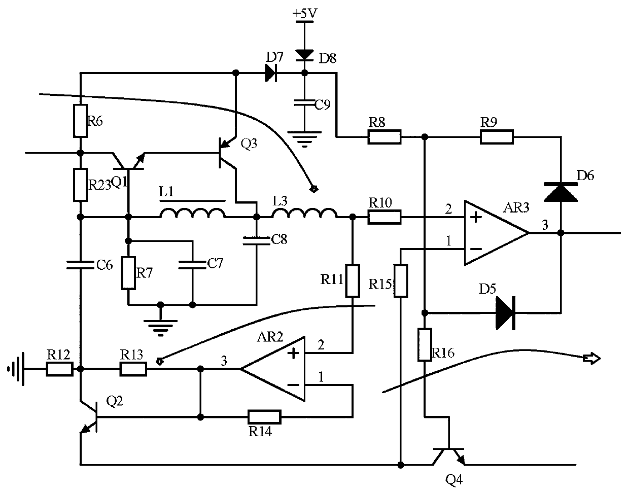
[0014] Embodiment 1, a signal compensation circuit for a water supply remote monitoring system, including a frequency selection input circuit, a feedback compensation circuit, and an operational amplifier output circuit, the frequency selection input circuit receives a signal input terminal for receiving signals from a control terminal in a water supply remote monitoring system For the signal within, the double-T frequency selection circuit composed of resistor R1~resistor R3 and capacitor C1 and capacitor C3 is used to filter out a single frequency signal, and at the same time, the operational amplifier AR1 is used to amplify in phase and then input into the feedback compensation circuit. The feedback compensation circuit uses Inductor L1, capacitor C7, and capacitor C8 form a filter circuit for filtering, and at the same time use transistor Q1 and transistor Q3 to form a switch circuit to filter out abnormal amplitude signals in the signal, and use power +5V to divide the volt...

Embodiment 2

[0017]Embodiment 2. On the basis of Embodiment 1, the operational amplifier output circuit uses the operational amplifier AR4 to amplify the signal in phase and output it, amplifies the signal power, ensures the compensation signal strength, and uses the voltage regulator tube D1 to stabilize the voltage and then output. That is to say, in the water supply remote monitoring system, the control terminal receives the signal and uses the compensation signal of the signal input terminal signal, and uses the compensation signal to prevent signal attenuation. The emitter of the transistor Q4, the other end of the resistor R18 is grounded, the non-inverting input terminal of the operational amplifier AR4 is connected to the resistor R17 and one end of the resistor R20, the other end of the resistor R17 is connected to the output terminal of the operational amplifier AR3, and the output of the operational amplifier AR4 Connect the other end of the resistor R20 with the resistor R22, on...

Embodiment 3

[0018] Embodiment 3, on the basis of Embodiment 1, the frequency selection input circuit receives the signal in the signal input terminal of the control terminal receiving signal in the water supply remote monitoring system, and uses resistors R1~R3 ​​and capacitors C1 and C3 to form a dual circuit. The T frequency selection circuit screens out a single frequency signal, the single frequency signal transmission is more stable, and prepares for the calibration signal of the feedback compensation circuit. At the same time, the op amp AR1 is used to amplify in phase and then input into the feedback compensation circuit. One end of the resistor R1 is connected to a capacitor. One end of C1 and the signal output port, the other end of resistor R1 is connected to resistor R3, one end of capacitor C3, the other end of resistor R3 is connected to resistor R5, one end of capacitor C2 and the non-inverting input end of op amp AR1, and the other end of resistor R5 Connect the collector of...


PUM


Abstract

The invention discloses a signal compensation circuit for a water supply remote monitoring system. The circuit comprises a frequency selection input circuit, a feedback compensation circuit and an operational amplifier output circuit, wherein the frequency selection input circuit receives a signal in a signal input end for receiving a signal by a control terminal in the water supply remote monitoring system; the feedback compensation circuit uses an inductor L1 and a capacitor C7,the capacitor C8 forms a filter circuit for filtering; meanwhile, the triode Q1 and the triode Q3 are used for forming a switching circuit to filter out abnormal amplitude signals in the signals; a compensation signal is improved for the output end of the comparator AR3 after a power supply + 5V is subjected to voltage division by a resistor R8; wherein the operational amplifier AR2 and the triode Q2 form a feedback circuit to feed back a signal to the inverting input end of the comparator AR3; and finally, the operational amplifier output circuit uses an operational amplifier AR4 to perform in-phase amplification on the signal and then outputs the signal, so that automatic frequency modulation calibrationcan be performed on the signal received by the control terminal in the water supply remote monitoring system by using the signal in the signal input end, signal compensation is performed, and frequency hopping and attenuation phenomena of the signal are prevented.

Description

technical field [0001] The invention relates to the field of circuit technology, in particular to a signal compensation circuit for a water supply remote monitoring system. Background technique [0002] In order to solve the problem of safe water supply for urban residents, many local water supply plants have built small water plants to collect groundwater or surface water and transport it to the water plant for treatment in the water plant. After reaching the drinking standard, it is transported to the main pipeline through a booster pump, and then the branch pipeline To send water to each urban household, in order to improve production efficiency and water supply management level, the water plant manager hopes to establish a set of remote monitoring and management system for water supply, that is, the signal compensation circuit for the remote monitoring system of water supply. However, the actual In the application, the signal in the signal input terminal of the control t...

Claims


Application Information

Patent Timeline
IPC IPC(8): H03H11/46
Inventor 张帆陈方亮王辉李伟魏琪黄丽娜周磊乔森刘杰黄亚楠张玉杜俊杰陈相森江佩彭丁丁赵尚
Owner ZHENGZHOU LITONG WATER CO LTD
Learn More