
A Parameter Calibration Method of the Optical Flow Catadioptric Camera Ranging System with Coaxial Center Distance

A distance measuring system and parameter calibration technology, which can be applied to measuring devices, instruments, etc., can solve the problem of large amount of optimization calculation, and achieve the effects of reducing machining accuracy and installation accuracy, improving distance measuring accuracy, and reducing influence.

Inactive Publication Date: 2017-01-25
ZHEJIANG UNIV
View PDF2 Cites 0 Cited by
  • Summary
  • Abstract
  • Description
  • Claims
  • Application Information

AI Technical Summary

Problems solved by technology

[0004] The traditional external parameter calibration is to estimate the rotation and translation between the mirror surface and the perspective camera by means of the calibration object; for the optical flow catadioptric camera ranging system with the coaxial center distance, the traditional external parameter calibration method has obvious disadvantages: first , the system is a highly nonlinear system, and the optical flow compensation for the angle installation error needs to be performed for each pixel one by one, and the optimization calculation is very heavy; secondly, the obtained compensation amount is only effective for a certain height, once the system is far from the experimental plane If the distance changes, a new optical flow compensation template is required

Method used


Image

  • A Parameter Calibration Method of the Optical Flow Catadioptric Camera Ranging System with Coaxial Center Distance
  • A Parameter Calibration Method of the Optical Flow Catadioptric Camera Ranging System with Coaxial Center Distance
  • A Parameter Calibration Method of the Optical Flow Catadioptric Camera Ranging System with Coaxial Center Distance

Examples


Embodiment Construction

[0016] The invention is more fully described below with reference to the accompanying drawings.

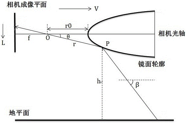
[0017] Such as figure 1 As shown, the camera ranging system in the present invention includes a rotating body mirror and a perspective camera coaxially placed opposite each other, the central symmetry axis of the rotating body mirror is in line with the optical axis of the perspective camera, and the vertex of the rotating body mirror is in line with the optical axis of the perspective camera. The distance between centers is fixed, the measured object is placed under the mirror surface of the rotating body, and the measured object is regarded as a space point. The incident light of the space point of the measured object is reflected by the mirror surface and imaged on the imaging plane of the perspective camera. Specular profile with equal optical flow properties. The iso-optical flow characteristic refers to the equidistant distribution of images of spatially equidistant points ...


PUM


Abstract

The invention discloses a method for calibrating parameters of an identical-axis-distance equal-luminous-flux catadioptric camera distance measuring system. According to the method, a central symmetrical axis of a rotary body mirror face is collinear with an optical axis of a perspective camera, a to-be-measured object is arranged below the rotary body mirror face, incidence light is reflected by the mirror face to be imaged by the perspective camera, and the rotary body mirror face has a mirror face profile with equal-luminous-flux characteristic. The method comprises the following steps of establishing a plurality of different simulation environments by adopting the camera distance measuring system, gradually increasing the distance from a to-be-measured object spatial point in each simulation environment to the optical axis, respectively acquiring luminous flux of the to-be-measured object spatial point in each simulation environment on an acquisition image of the perspective camera, and re-fitting the relation between the axis distance and the luminous flux. According to the method, the system is subjected to the parameter calibration, the influence of the processing precision and installation precision on the characteristics of the mirror face can be alleviated under the non-ideal configuration situation of the system, and the distance measuring precision can be improved. Compared with the traditional external parameter calibration method, the method is simpler, more convenient and more effective.

Description

technical field [0001] The invention relates to a parameter calibration method of a ranging system. Specifically, it relates to a method for calibrating the parameters of a coaxial center distance equal optical flow catadioptric camera ranging system. Background technique [0002] At present, omnidirectional cameras commonly used in video surveillance, robot navigation, video conferencing and scene reconstruction are mostly camera ranging systems composed of traditional perspective cameras and reflective mirrors. The use of reflective mirrors makes omnidirectional cameras have large field of view imaging characteristics . According to whether it satisfies the single-viewpoint characteristic, omnidirectional cameras can be divided into single-viewpoint catadioptric cameras and non-single-viewpoint catadioptric cameras. Since the installation of the perspective camera and the mirror surface will be misaligned to a certain extent in practical applications, the non-single-view...

Claims


Application Information

Patent Timeline
Patent Type & Authority Patents(China)
IPC IPC(8): G01C25/00
CPCG01C25/00
Inventor 项志宇马子昂
Owner ZHEJIANG UNIV
Learn More