CPLD-based oscilloscope display circuit for observing chaotic system bifurcations
A chaotic system and display circuit technology, applied in the direction of digital variable display, etc., can solve the problems of slow observation speed and achieve the effects of low cost, convenient operation and fast measurement speed
- Summary
- Abstract
- Description
- Claims
- Application Information
AI Technical Summary
Problems solved by technology
Method used
Image
Examples
Embodiment 1
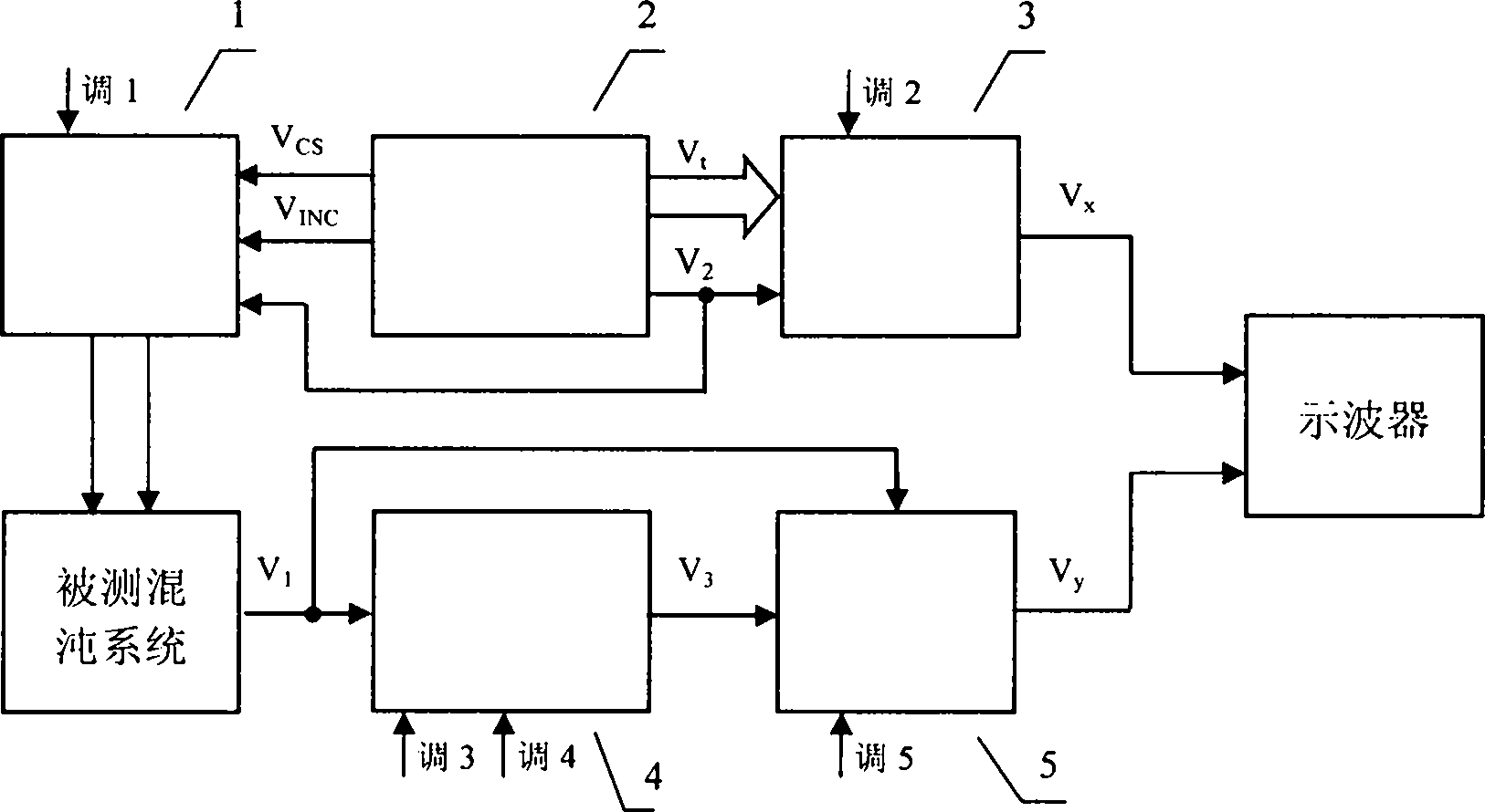
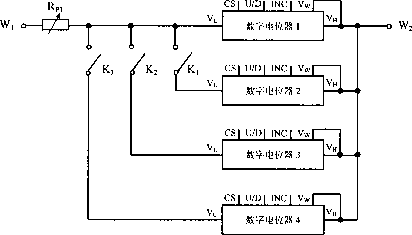
[0021] Such as figure 1 As shown, a CPLD-based oscilloscope display circuit for observing the bifurcation of a chaotic system includes a controllable resistor network 1, a CPLD signal circuit 2, a parameter signal circuit 3, an acquisition signal position circuit 4 and an acquisition signal circuit 5, and a CPLD signal circuit 2 Connect the controllable resistance network 1 and the parameter signal circuit 3 respectively, and the acquisition signal position circuit 4 is connected to the acquisition signal circuit 5, and the two external terminals of the controllable resistance network 1 are connected to both ends of the resistance to be measured of the chaotic system under test to obtain the signal The position circuit 4 and the acquisition signal circuit 5 simultaneously receive the signal V generated by the chaotic system under test 1 , the parameter signal circuit 3 outputs the signal V sent to the X-axis input terminal of the oscilloscope x , to obtain the signal V output...
Embodiment 2
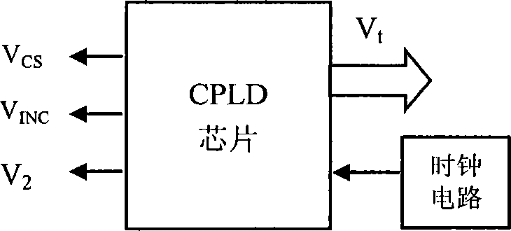
[0029] combine image 3 , introduce the CPLD signal circuit part of the present invention below:
[0030] The purpose of the CPLD signal circuit is to generate three digital signals to control the change of the resistance value in the controllable resistor network, and at the same time generate an 8-bit digital signal V t It is sent to the parameter signal circuit to generate the oscilloscope level signal V that varies with the parameters of the system under test x .
[0031] CPLD signal circuit is composed of CPLD chip and clock circuit. The clock circuit generates a 50MHz clock pulse signal for the CPLD chip to work. The CPLD chip is programmed by Verilog, and then downloaded to the EPM240 chip of the ALTERA Max II series after being compiled by Quartus II, that is, the CPLD chip is an internal circuit formed according to the layout and wiring of the program. The CPLD chip has four output ports, one of which outputs a digital signal V CS ; One of the output terminals ou...
Embodiment 3
[0037] to combine Figure 4 , introduce the parameter signal circuit part of the present invention below:
[0038] The purpose of the parameter signal circuit is to generate the signal V that is fed into the X-axis of the oscilloscope x ,See figure 1 and Figure 4 shown.
[0039] The parameter signal circuit is composed of a digital-to-analog conversion circuit and a signal selection circuit. The parameter signal circuit has two input terminals and one output terminal. One input receives the 8-bit sawtooth digital signal V generated by the CPLD signal circuit t , the other input end, receiving CPLD signal circuit to generate 1-bit digital signal V 2 , the output terminal outputs the signal V x .
[0040] The digital-to-analog conversion circuit is composed of a digital-to-analog converter, a first operational amplifier A 1 and reference voltage V R1 consist of. The input terminal of the digital-to-analog converter receives the 8-bit sawtooth digital signal V generat...
PUM
 Abstract
Description
Claims
Application Information
 - R&D
- Intellectual Property
- Life Sciences
- Materials
- Tech Scout
- Unparalleled Data Quality
- Higher Quality Content
- 60% Fewer Hallucinations
Browse by: Latest US Patents, China's latest patents, Technical Efficacy Thesaurus, Application Domain, Technology Topic, Popular Technical Reports.
© 2025 PatSnap. All rights reserved.Legal|Privacy policy|Modern Slavery Act Transparency Statement|Sitemap|About US| Contact US: help@patsnap.com


