
An Indoor Reference Positioning Method Based on Radio Frequency Identification Technology

A technology of radio frequency identification technology and positioning method, which is applied in the direction of positioning, cooperative operation devices, and measuring devices, which can solve the problems of high cost of locator terminals, inability to be widely promoted, and low RSSI accuracy, so as to overcome the distortion of positioning accuracy, Easy to expand, accurate and reliable positioning information

Active Publication Date: 2017-01-04
BEIHANG UNIV
View PDF3 Cites 0 Cited by
  • Summary
  • Abstract
  • Description
  • Claims
  • Application Information

AI Technical Summary

Problems solved by technology

However, when the GPS receiver works indoors, the signal is greatly attenuated due to the influence of buildings, and the cost of the locator terminal is relatively high
[0004] 2. Infrared technology: Active tags based on diffuse infrared technology can be used for indoor positioning, but it requires that the object to be tested must be in a straight line with the infrared reader, and the positioning distance is relatively short, so the practical application is of little significance
The system applying this kind of technology is easy to build, but the measurement accuracy is average and needs to be further improved
[0006] 4. Ultrasonic technology: At present, the successful use of this technology can indeed achieve high positioning accuracy, but it requires a lot of infrastructure support, the cost is expensive, and it cannot be widely promoted
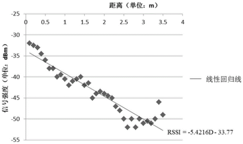
However, due to the complexity of the wireless signal propagation model in the indoor environment, the accuracy of RSSI is generally relatively low.

Method used

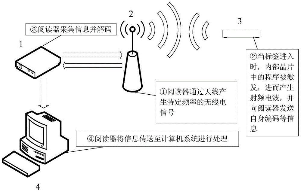

Image

  • An Indoor Reference Positioning Method Based on Radio Frequency Identification Technology
  • An Indoor Reference Positioning Method Based on Radio Frequency Identification Technology
  • An Indoor Reference Positioning Method Based on Radio Frequency Identification Technology

Examples


Embodiment Construction

[0063] specific implementation plan

[0064] The method of the present invention will be further described in detail below in conjunction with the accompanying drawings and examples.

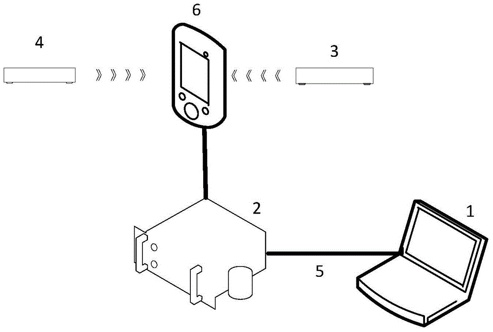
[0065] like figure 1 , 2 , the present invention is a kind of indoor reference positioning method based on radio frequency identification technology, and its equipment comprises: Information Server (Information Server, IS) 2, is used for carrying out the control function and data storage function of whole system; Client Computer (Client Computer, CC ) 1, which is connected to the information server 2 through a local area network 5, and is used to provide a user-oriented operation interface; a portable RFID reader (Mobile RFID Reader, MRR) 6, carried by field staff; a plurality of RFID tags to be tested (Object Tag, OT) 3, which is set on each object to be tracked, and each object has only one RFID tag to be tested 3, which is used to uniquely identify the object, and the object tag is electron...


PUM


Abstract

An indoor reference positioning method based on radio frequency identification technology, one: determine the relationship between signal strength and distance through the RSSI positioning algorithm; two: arrange RFID reference tags; three: carry RFID readers to read the reference tags and the tags sent by the test Signal strength; 4: Sorting the signal strength of the reference tags; 5: Choose the three with the largest signal strength, and get the distance between the reference tag and the reader as r1, r2, r3 and the distance between the tag to be tested and the reader d1; 6: Take Take three reference tags as the center, make a circle with r1, r2, and r3 as the radius, and the intersection point of the three circles is the position of the reader; 7: Repeat steps 3 to 6 twice to obtain the new position of the reader and the location of the tag to be tested and The distance between readers is d2, d3; 8: Take the three different positions of the reader as the center, and make a circle with d1, d2, and d3 as the radius, and the intersection of the three circles is the position of the label to be tested; 9: Repeat step 3 to 8. Obtain the positions of other tags to be tested.

Description

technical field [0001] The invention relates to an indoor reference positioning method based on radio frequency identification technology (hereinafter referred to as "RFID": radio frequency identification), which belongs to the field of radio frequency identification technology. Background technique [0002] With the development of wireless communication technology, people's demand for positioning is increasing, especially in complex indoor environments, such as airport halls, exhibition halls, warehouses, supermarkets, libraries, parks, underground parking lots, mines, etc. It is necessary to use mobile terminals to provide location information for personnel, facilities and objects. Therefore, many solutions for indoor positioning technology have been proposed, as follows: [0003] 1. Indoor GPS positioning technology: GPS is currently the most widely used positioning technology. However, when the GPS receiver works indoors, the signal is greatly attenuated due to the inf...

Claims


Application Information

Patent Timeline
Patent Type & Authority Patents(China)
IPC IPC(8): G01S5/12G06K17/00
Inventor 孙占磊杨亚男王伟王帅赵罡
Owner BEIHANG UNIV
Learn More