Eddy-current loss analysis method for permanent magnet wind generators

A wind turbine and eddy current loss technology, applied in the field of simulation, can solve problems such as large actual deviation, reduced accuracy, and difficult evaluation of correction coefficients

Active Publication Date: 2014-12-03
INNER MONGOLIA UNIV OF TECH
View PDF3 Cites 19 Cited by
  • Summary
  • Abstract
  • Description
  • Claims
  • Application Information

AI Technical Summary

Problems solved by technology

[0013] From 2008 to 2011, Xing Junqiang’s research team from Shenyang University of Technology, in the research on rotor loss and ventilation and heat dissipation of high-speed permanent magnet motors, approximately believed that the eddy current loss of the rotor was mainly concentrated on the surface of the rotor, and that it was generated by the high-frequency eddy current loss on the surface of the sheath. The eddy current loss in the sleeve is equivalent to the analytical calculation method of a rectangular thin surface under a pole pitch distribution, which can qualitatively analyze the approximate distribution of eddy current loss, but the accuracy is poor
In 2013, Intel Engineering Simulation Technology (Dalian) Co., Ltd. proposed a patent application 201310343818.9 for a method for analyzing the temperature rise and heat dissipation of permanent magnet synchronous motors based on multi-field coupling technology. This patent application applied the multi-field coupling method to permanent magnets for the first time. The temperature rise analysis of the motor has great influence, but the main disadvantage is that the three-field coupling and two sets of models lead to the load loss phenomenon in the load transfer process, and the heat transfer coefficient as the link parameter between the flow field and the temperature field is ignoring the gas The influence of the gap radial speed gradient on it is obtained, and the air gap speed is approximately considered to be the rotor speed, and the convective heat transfer coefficient is calculated by using the traditional empirical formula, so the accuracy of the result is reduced due to the approximation of the intermediate pro

Method used


Image

  • Eddy-current loss analysis method for permanent magnet wind generators
  • Eddy-current loss analysis method for permanent magnet wind generators
  • Eddy-current loss analysis method for permanent magnet wind generators

Examples


Embodiment Construction

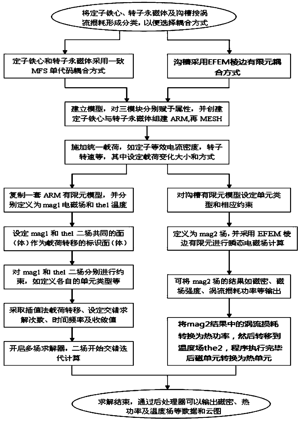
[0029] Below in conjunction with accompanying drawing, the present invention will be further described, as figure 1It is a schematic flow chart of the eddy current loss analysis method in the permanent magnet wind power generator of the present invention, as shown in the figure, the steps of the method are: (1) classify the three modules that produce eddy current loss, due to the difference between the stator core and the rotor permanent magnet The eddy current loss is caused by the alternating magnetic field formed by the interaction between the main magnetic field and the additional magnetic field to form a loop on its surface. The magnetothermal conversion process is relatively simple, so the MFS single-code two-way coupling method is used to directly couple the electromagnetic field and the temperature field for simulation calculation; The eddy current loss of the groove is relatively complicated, not only related to the alternating magnetic field, but also related to the g...


PUM


Abstract

The invention discloses an eddy-current loss analysis method for permanent magnet wind generators. The eddy-current loss analysis method includes the steps of 1), dividing an acquisition mode of eddy-current losses into an MFS single-code coupling mode and an EFEM edge finite element coupling mode according to difference in formation mechanism and component of eddy-current losses; 2), respectively combining component models with the same coupling mode prior to mesh partition; 3), setting unified load for the combined model; 4), performing load transferring on the models established in the MFS single-code coupling mode by an interpolation method, and solving field distribution in staggered iteration through a multi-field solver; 5), solving transient electromagnetic fields and temperature fields by a parallel algorithm; 6), reflecting the electromagnetic fields and the temperature fields of different component models on the corresponding models. An electromagnetic field and temperature field coupling method of single-code two-way coupling analysis and one-way coupling analysis of the edge finite element coupling method are applied to subregional-type acquisition of the eddy-current losses of stator cores, rotor permanent magnets and grooves, and consequently, the eddy-current losses are converted into thermal power and are reflected in temperature field distribution accurately and visually.

Description

technical field [0001] The invention belongs to the field of simulation technology, and specifically relates to an analysis method for eddy current loss in permanent magnet wind power generators widely used in the field of new energy applications, that is, an analysis method for eddy current loss in permanent magnet wind power generators. Background technique [0002] At present, due to the depletion of non-renewable energy and other factors, wind energy has become one of the most promising green energy in the 21st century. With its huge commercial potential and environmental protection benefits, it has been widely valued and developed by all countries in the world. As a sustainable clean energy source, wind power technology has a bright future. This new source of electricity will gradually enter people's homes and eventually become a part of public life. [0003] With the expansion of the application range of small permanent magnet wind turbines, the performance of the moto...

Claims


Application Information

Patent Timeline
IPC IPC(8): G06F17/50
CPCY02B10/30
Inventor 温彩凤汪建文孙素丽张立茹
Owner INNER MONGOLIA UNIV OF TECH
Why Eureka
Try Eureka