Novel CNC wire cutting machine

A wire cutting machine and a new type of technology, applied in the field of CNC machine tools, can solve problems such as discharge corrosion, affecting the machining accuracy of workpieces, and inability to adjust the moving speed of transverse plates and longitudinal poles.

Active Publication Date: 2014-12-10
TAICANG SHUNCHANG FORGE
View PDF8 Cites 0 Cited by
  • Summary
  • Abstract
  • Description
  • Claims
  • Application Information

AI Technical Summary

Problems solved by technology

[0002] CNC wire cutting machine, also known as CNC wire cutting machine tool, uses a moving metal wire (molybdenum wire, tungsten wire or copper wire, etc.) Pulse current to generate pulse discharge for cutting processing; during the processing, the electrode wire passes through the pre-drilled small hole on the workpiece, and is driven by the wire-feeding mechanism to move axially through the guide wheel, and the workpiece passes through the insulating plate Installed on the workbench, the CNC device moves along the X and Y coordinate directions according to the instructions of the processing program to synthesize the required plane trajectory such as straight lines and arcs. While moving, discharges are continuously generated between the wire electrode and the workpiece. Corrosion phenomenon, the working fluid is injected through the nozzle to take away the galvanic corrosion products, and finally leaves the slit trajectory line cut by the filament on the metal workpiece, so as to meet the processing requirements of separating one part of the metal from another part of the metal; the existing The most advanced CNC wire cutting machine, its workbench includes a transverse plate and a longitudinal plate, the transverse plate and the longitudinal plate are superimposed on each other through the roller shaft, and the movement in the two coordinate directions of X and Y is realized through the traction device, but this method not only coordinates The precision is limited, and the moving speed of the horizontal plate and the vertical pole cannot be adjusted. At the same time, during the wire cutting process, because the traction device does not have the function of limiting, it is easy to cause the table to shake and affect the processing accuracy of the workpiece.

Method used


Image

  • Novel CNC wire cutting machine
  • Novel CNC wire cutting machine
  • Novel CNC wire cutting machine

Examples


Embodiment Construction

[0018] The specific implementation manners of the present invention will be further described in detail below in conjunction with the accompanying drawings and embodiments. The following examples are used to illustrate the present invention, but are not intended to limit the scope of the present invention.

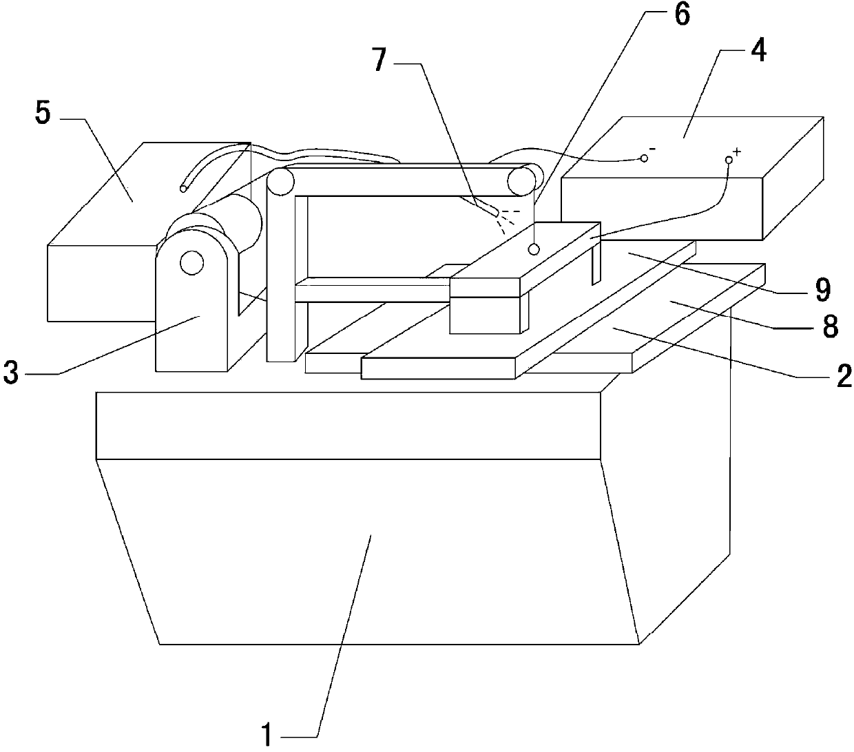
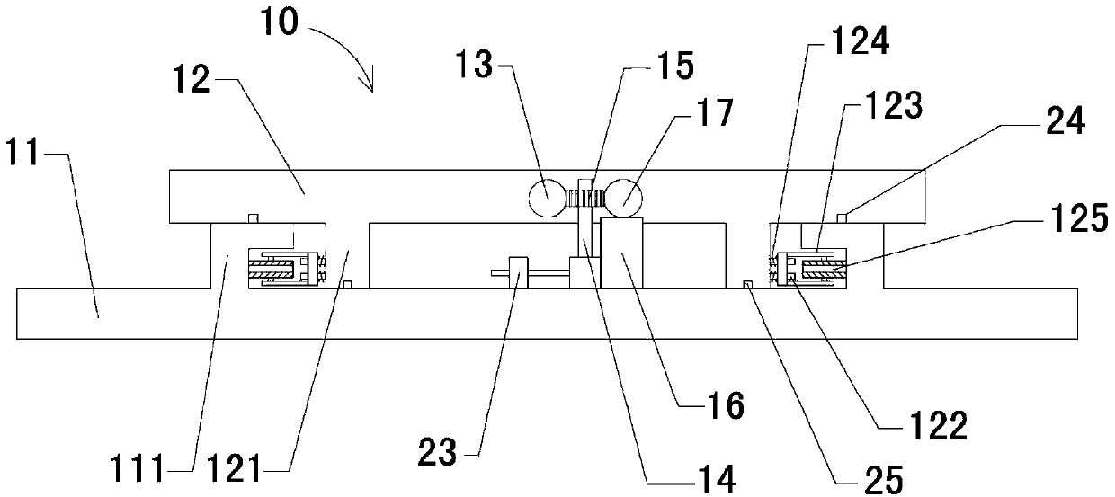
[0019] see Figure 1 to Figure 3 As shown, a new CNC wire cutting machine includes a machine tool body 1, a workbench 2, a wire-feeding mechanism 3, a high-frequency pulse power supply 4, a liquid supply system 5, and an electrode wire 6. The workbench 1 and the wire-feeding mechanism 3 are set on On the machine tool body 1, an electrode wire 6 is wound on the wire-feeding mechanism 3, and the electrode wire 6 is electrically connected to the high-frequency pulse power supply 4, and the nozzle 7 connected to the liquid supply system is installed on the wire-feeding mechanism 3; the workbench includes a horizontal Plate 8, longitudinal plate 9 and displacement device 10, t...


PUM

PropertyMeasurementUnit
angleaaaaaaaaaa

Abstract

The invention relates to a novel CNC wire cutting machine which can effectively improve the coordinate accuracy of a horizontal plate and a longitudinal plate. The novel CNC wire cutting machine comprises a machine tool body, a workbench, a wire walking mechanism, a high-frequency pulse power supply, a liquid supply system and an electrode wire. The workbench comprises a horizontal plate, a longitudinal plate and a displacement device. The horizontal plate is arranged on the top face of the machine tool body through the displacement device. The longitudinal plate is arranged on the top of the horizontal plate through the displacement device. The displacement device comprises a bottom plate and a top plate. A thread rod is fixed at the end of the top plate in a parallel mode. A middle rotating shaft is vertically arranged on the bottom plate. A worm wheel is arranged on the middle rotating shaft through a bearing. The worm wheel is meshed with a thread face of the thread rod. A motor box is arranged on the bottom plate. The motor box comprises a speed reducing motor, a worm and a worm adjusting sleeve. One end of the worm is arranged at the output end of the speed reducing motor. Spiral-shaped gear teeth meshed with the worm wheel are arranged on the worm. The thickness of the gear teeth are gradually increased from one end to the other end in the axial direction. The other end of the worm moves relatively in the axial direction in a worm adjusting sleeve.

Description

technical field [0001] The invention relates to a numerically controlled machine tool, in particular to a novel CNC wire cutting machine. Background technique [0002] CNC wire cutting machine, also known as CNC wire cutting machine tool, uses a moving metal wire (molybdenum wire, tungsten wire or copper wire, etc.) Pulse current to generate pulse discharge for cutting processing; during the processing, the electrode wire passes through the pre-drilled small hole on the workpiece, and is driven by the wire-feeding mechanism to move axially through the guide wheel, and the workpiece passes through the insulating plate Installed on the workbench, the CNC device moves along the X and Y coordinate directions according to the instructions of the processing program to synthesize the required plane trajectory such as straight lines and arcs. While moving, discharges are continuously generated between the wire electrode and the workpiece. Corrosion phenomenon, the working fluid is ...

Claims


Application Information

Patent Timeline
Patent Type & Authority Applications(China)
IPC IPC(8): B23H7/02
Inventor 钱仁元
Owner TAICANG SHUNCHANG FORGE
Why Eureka
Try Eureka