Machine tool special for riveting globe joint

A special machine tool and ball joint technology, applied in the field of ball joint riveting and pressing special machine tools, can solve the problems of low production efficiency, product rework and maintenance, ball joint too loose, etc., to save production costs, improve production efficiency, and eliminate the effects of rework.

Active Publication Date: 2014-12-10
ZHEJIANG LIFUDE MACHINERY
View PDF5 Cites 7 Cited by
  • Summary
  • Abstract
  • Description
  • Claims
  • Application Information

AI Technical Summary

Problems solved by technology

The riveting edge of the upper cover has a pressing force on the backing plate. If the deformation of the riveting edge of the upper cover is too large when riveting the upper cover, the pressure on the backing plate will be large. If the contact pressure between the head seats is high, the rotation of the ball joint will be inflexible; on the contrary, if the deformation of the riveted edge of the upper cover is too small, then the pressure on the backing plate will be small, and the ball head of the ball head and the ball head seat will If the contact pressure between them is small, the rotation of the ball joint will be too loose and the gap will be too large
Therefore, the current method used is: firstly perform the riveting process on the ball joint product, and then take it to a special torque testing platform to detect the rotational torque of the ball joint, and the production efficiency is low; the more serious problem is that after the riveting process Finally, there will be a lot of ball joint products with unqualified torque, which will lead to rework and repair of a large number of products, and the production cost will be high

Method used


Image

  • Machine tool special for riveting globe joint
  • Machine tool special for riveting globe joint
  • Machine tool special for riveting globe joint

Examples


Embodiment Construction

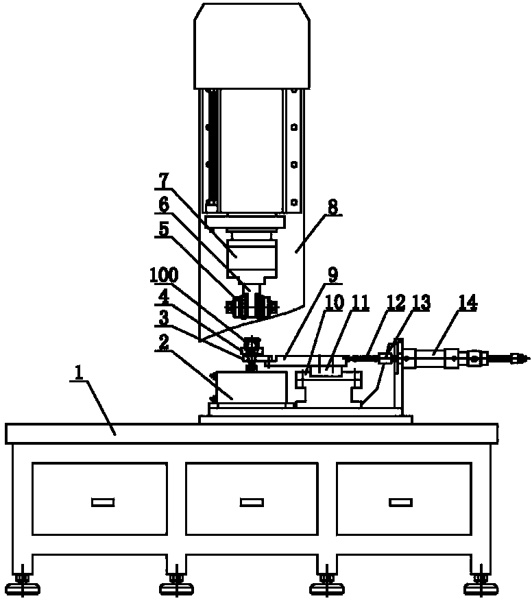
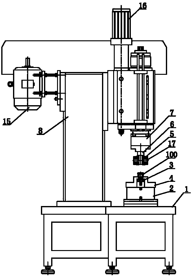
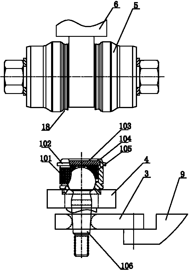
[0015] As shown in the figure, the ball joint riveting special machine tool of the present invention is used for the riveting assembly of ball joint products. The ball joint products include ball head rod 106, ball head seat 105, backing plate 103, shell 101 and upper cover 102, The ball head of the ball head rod 106, the ball head seat 105 and the backing plate 103 are located in the inner hole of the shell 101, the upper cover 102 is connected to the upper opening of the shell 101, and the upper cover 102 is riveted to form an upper cover riveting edge 104, and the upper cover is riveted Crimping 104 defines the head of ball head shaft 106 , head seat 105 and backing plate 103 within housing 101 . The special machine tool for ball joint riveting of the present invention includes installation 4, riveting head 5, power head 7, servo motor 16 and torque detection device, and the mounting seat 4 is arranged on the horizontal machine body 1 for ball joint workpiece 100. Installat...


PUM


Abstract

The invention discloses a machine tool special for riveting a globe joint. The machine tool comprises an installation base, a riveting head and a power head, wherein the riveting head is arranged over the installation base, and the riveting head is connected to the bottom of the power head and driven by the power head to rotate. The machine tool is characterized by further comprising a servo motor and a torque detecting device, the servo motor pushes the power head and the riveting head to conduct vertical adjustment during working, the torque detecting device pushes a ball rod of a globe joint workpiece to swing in a leftward-rightward reciprocating mode during working, the torque detecting device comprises a positioning ring, a connecting plate, a torque sensor and a push-pull part, the positioning ring is used for buckling the ball rod of the globe joint workpiece, one end of the connecting plate is connected with the positioning ring, the other end of the connecting plate is connected with the torque sensor, the other end of the torque sensor is connected with the push-pull part, and the output end of the torque sensor is electrically connected with the servo motor. By the adoption of the machine tool, the driving torque requirement of the globe joint workpiece can be met as soon as the globe joint workpiece is riveted and assembled, production efficiency is improved, reworking of products is avoided, and production cost is saved.

Description

technical field [0001] The invention relates to a ball joint riveting machine tool specially used for riveting and assembling ball joint products. Background technique [0002] Ball joint products are named for their flexible rotation like joints. Ball joint products are widely used in transmission machinery and construction machinery. For the ball joint used in the front and rear axles of the vehicle, its general structure is: including the ball joint, the ball seat, the backing plate, the shell and the upper cover, the ball head of the ball joint, the ball seat and the backing plate are located in the inner hole of the shell The upper cover is connected to the opening of the upper end of the shell, and the upper cover is riveted to form the upper cover riveting edge, and the upper cover riveting edge defines the ball head of the ball head, the ball head seat and the backing plate in the shell. The riveting edge of the upper cover has a pressing force on the backing plate....

Claims


Application Information

Patent Timeline
Patent Type & Authority Applications(China)
IPC IPC(8): B23P19/02
CPCB23P19/006B23P19/02G01L3/00
Inventor 陈守福陈守明陈小海
Owner ZHEJIANG LIFUDE MACHINERY
Why Eureka
Try Eureka