Array electric fluid jet printing head characterized by independently controllable nozzle jet and realization method of independent control of jet of nozzles

A printing head and electrofluid technology, applied in printing and other directions, can solve problems such as inability to be used in large-scale integration and complex structure, and achieve the effect of simple structure and guaranteed positioning

Active Publication Date: 2014-12-10
HUAZHONG UNIV OF SCI & TECH
View PDF10 Cites 34 Cited by
  • Summary
  • Abstract
  • Description
  • Claims
  • Application Information

AI Technical Summary

Problems solved by technology

[0005] In view of the above defects or improvement needs of the prior art, the object of the present invention is to provide an independently controllable arrayed jet printing head and a method for realizing independently controllable jetting of an arrayed electrofluid jet printing head. The field strength of the layout of each nozzle of the print head is adjusted to realize the independent controllability of the spraying of each nozzle, and solve the existing problems of complex structure and inability to be used in large-scale integration of the independent spraying control of the print head.

Method used


Image

  • Array electric fluid jet printing head characterized by independently controllable nozzle jet and realization method of independent control of jet of nozzles
  • Array electric fluid jet printing head characterized by independently controllable nozzle jet and realization method of independent control of jet of nozzles
  • Array electric fluid jet printing head characterized by independently controllable nozzle jet and realization method of independent control of jet of nozzles

Examples


Embodiment Construction

[0031] In order to make the object, technical solution and advantages of the present invention clearer, the present invention will be further described in detail below in conjunction with the accompanying drawings and embodiments. It should be understood that the specific embodiments described here are only used to explain the present invention, not to limit the present invention. In addition, the technical features involved in the various embodiments of the present invention described below can be combined with each other as long as they do not constitute a conflict with each other.

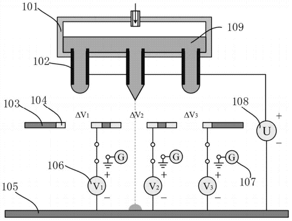
[0032] figure 1 It is a schematic diagram of the principle of the multi-level voltage method in the present invention. The arrayed electrofluid jet printing head is composed of 101 and 103, 101 is an arrayed nozzle, and 103 is a guiding electrode layer. 102 is a stainless steel capillary nozzle, 104 is a conductive ring, 105 is a receiving plate, 106 is a DC voltage source, 107 is a ground term...


PUM


Abstract

The invention discloses an array electric fluid jet printing head characterized by independently controllable nozzle jet. The array electric fluid jet printing head comprises a guide electrode layer arranged between a nozzle array and a receiving plate, and a plurality of round holes corresponding to nozzles in number are formed in the guide electrode layer; the centers of the round holes are collinear with the centers of the nozzles; a circle of conducting ring is coaxially disposed on the outer periphery of each round hole in the guide electrode layer, and is connected with one voltage source; and the nozzle array is connected with the jet voltage sources; and the voltage value of each voltage source is properly adjusted, so that the voltage differences of the nozzles required for jet printing and the corresponding conducting rings are greater than the voltage differences of the remaining nozzles, the field strength of the nozzles for jet is greater than the field strength needed to start the jetting, the field strength of the nozzles not required for jetting is lower than the field strength needed to start the jetting, and the independent control of all the nozzles can be realized. The invention further discloses a realization method of the independent control of the jet of the nozzles. The array electric fluid jet printing head and the realization method can solve the problems of complex structure and incapability of large-scale integrated use in the conventional independent jet control to printing heads.

Description

technical field [0001] The invention relates to the technical field of electrofluid jet printing, in particular to an arrayed electrofluid jet printing head and a method for realizing independent controllable ejection of the arrayed electrofluid jet print head. Background technique [0002] Complex microscale structures can be used in many fields, such as printed electronics, organic / flexible electronic devices, multifunctional sensors, etc., so their preparation process has attracted much attention in recent years. As a non-contact patterning process, inkjet printing and electrofluid jet printing can deposit micro-scale structures on the substrate, and compared with photolithographic patterning processes, they have the advantages of no mask, material saving, environmental friendliness, and convenient operation. , which is considered to be the best solution. However, traditional inkjet printing technologies (such as piezoelectric printing and thermal foam printing) usually ...

Claims


Application Information

Patent Timeline
Patent Type & Authority Applications(China)
IPC IPC(8): B41J2/045
Inventor 黄永安尹周平潘艳桥郭磊
Owner HUAZHONG UNIV OF SCI & TECH
Why Eureka
Try Eureka