Full-automatic bundling machine for small-bundle wire

A strapping machine, fully automatic technology, applied in the direction of strapping materials, strapping machine parts, paper/cardboard containers, etc. Suitable for automatic binding and other problems, to achieve the effect of saving binding materials, reliable performance and short distance

Inactive Publication Date: 2014-12-10
SHAOYANG UNIV
View PDF9 Cites 7 Cited by
  • Summary
  • Abstract
  • Description
  • Claims
  • Application Information

AI Technical Summary

Problems solved by technology

[0006] The above two kinds of steel bar binding machines have the following disadvantages. First, due to the use of bevel gear transmission, the binding wire is spirally wound, resulting in a complicated body structure; Because the wire feeding channel is long and not in a straight line, the wire feeding resistance is large, which wastes energy; fourth, the distance between the broken wire point and the knot is long, so the wire tie will be wasted; fifth, the wire reel is small, and it is easy to replace the wire reel. Affect work efficiency, not suitable for fully automatic binding on wire rod production line

Method used


Image

  • Full-automatic bundling machine for small-bundle wire
  • Full-automatic bundling machine for small-bundle wire
  • Full-automatic bundling machine for small-bundle wire

Examples


Embodiment Construction

[0028] The present invention will be described in detail below in conjunction with the accompanying drawings.

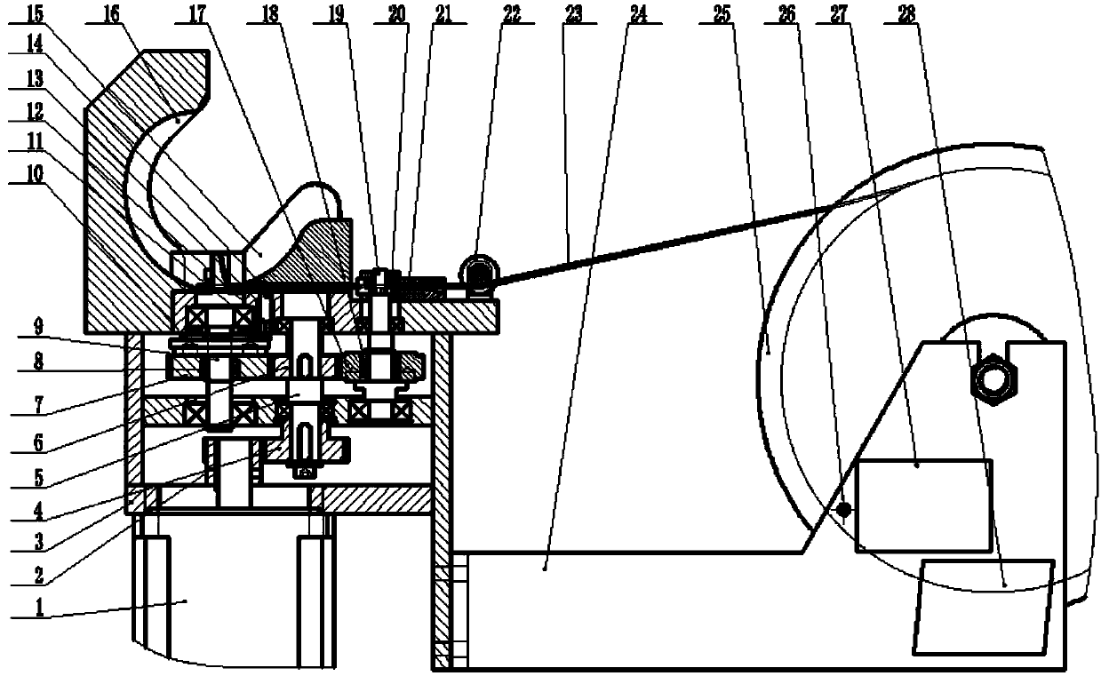
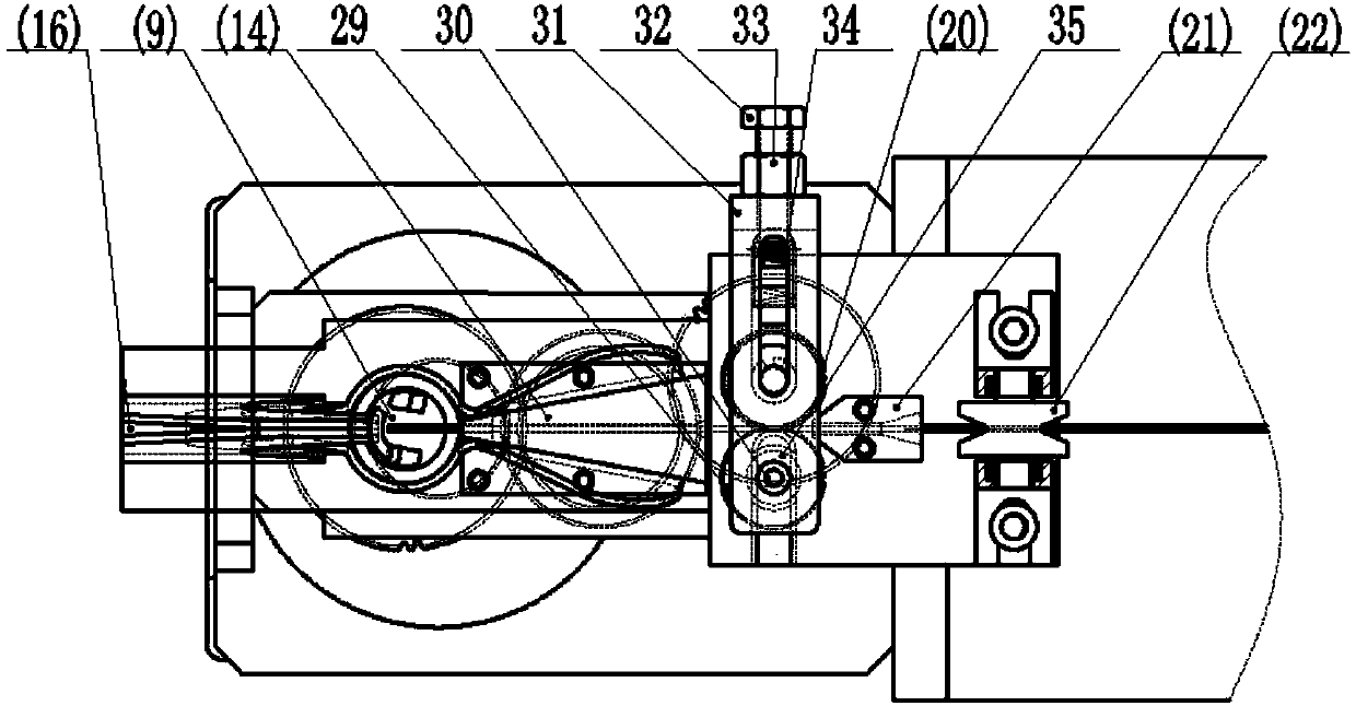
[0029] refer to figure 1 , figure 2 , Fully automatic bundling machine for small bundles of wire, composed of drive control components, transmission components, wire storage components, wire feeding and rounding components, broken wire and knotting components.

[0030] The drive control assembly is located at the bottom of the baler, and consists of a servo motor 1, a servo motor driver 27 and a servo motor controller 28. The output shaft of the servo motor 1 is fixedly connected to the gear 1 2, and the servo motor driver 27 is connected to the servo motor 1 before and after. and servo motor controller 28;

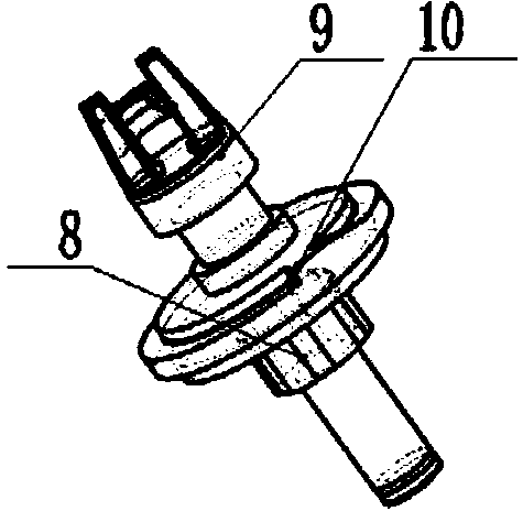
[0031] The transmission assembly is located in the middle of the frame 3 of the baler, including gear one 2, gear two 4, main shaft 5, gear three 6, gear four 7, one-way bearing one 8, knotting shift fork shaft 9, gear five 17, one-way bearing two 18, active...


PUM


Abstract

The invention relates to a full-automatic bundling machine for a small-bundle wire. The full-automatic bundling machine comprises a driving control assembly, a transmission assembly, a wire storage assembly, a wire feeding and reeling assembly and a wire breaking and knotting assembly. The driving control assembly is located on the lower portion of the bundling machine, the transmission assembly is located in the middle of a machine frame, the wire storage assembly is located at the back of the bundling machine, the two sides of a main shaft are provided with a knotting shifting fork shaft and a driving wire feeding gear shaft, the knotting shifting fork shaft and the driving wire feeding gear shaft are parallel to the main shaft in space, and three shafts are provided with transmission gears respectively. The two sides of a wire cutting tool apron and the two sides of a C-shaped arc-shaped face of the machine frame are provided with wire reeling guard bars respectively. The wire cutting tool apron is provided with slots for tying wires to pass through, and outlets of the slots are aligned with gaps in a shifting fork head on the knotting shifting fork shaft. A wire cutting cam and a fourth gear are attached together, the upper end of a wire cutting tool penetrates through a U-shaped groove, located in the upper portion, of the wire cutting tool apron, the lower end of the wire cutting tool is connected with a wire cutting tool adjusting nut to be connected with the machine frame in a sliding mode, and a tool handle of the wire cutting tool is attached to the wire cutting cam under the effect of springs. By means of the full-automatic bundling machine for the small-bundle wire, a servo motor is used for achieving the full-automatic wire feeding, wire breaking and wire knotting functions, the structure is simple, performance is reliable, wire tying materials are saved, the automatic degree and the production efficiency are high, and full-automatic bundling of the small-bundle wire on a wire rolling production line is achieved.

Description

[0001] technical field [0002] The invention relates to a fully automatic bundling machine for small bundles of wires, in particular to a bundling machine for bundling small bundles of straight wires on a wire production line, so as to realize online automatic bundling and collection of small bundles of wires. Background technique [0003] At present, the automatic strapping machine produced in China is aimed at large bundles of wire rods, and the strapping raw material used is steel strips. After the strapping steel straps are tightened, the shape of the lap joints of the steel straps is destroyed, and the friction is increased to achieve the purpose of bundling. For the bundling of small bundles of wire rods, because the bundling diameter is too small, it is not suitable to use steel strips as the bundling raw material. At present, steel wire is used as the binding machine of binding raw material, only for the binding of hand-held electric steel bars in engineering constr...

Claims


Application Information

Patent Timeline
Patent Type & Authority Applications(China)
IPC IPC(8): B65B13/04B65B13/26
Inventor 戴小标张红梅袁文华刘学敏
Owner SHAOYANG UNIV
Why Eureka
Try Eureka