Basement sump structure

A sump and basement technology, applied in the field of building waterproofing and drainage, can solve the problems of increasing economic cost and construction period, reducing economic benefits, weakening the stability of the bottom plate structure, etc.

Active Publication Date: 2014-12-10
SHENZHEN GENERAL INST OF ARCHITECTURAL DESIGN & RES
View PDF5 Cites 3 Cited by
  • Summary
  • Abstract
  • Description
  • Claims
  • Application Information

AI Technical Summary

Problems solved by technology

Such a setting makes the basement floor no longer a complete planar structure, and the connection between the basement floor and the side wall of the sump and the connection between the side wall of the sump and the bottom of the sump are all folded plates. The force is interrupted at the opening of the opening, causing the opening of the bottom plate to be squeezed and deformed due to the force on the ground, and the structural stability of the bottom plate is weakened
[0005] (2) Design and construction are complicated, reducing economic benefits
Due to the integrated structure o

Method used


Image

  • Basement sump structure
  • Basement sump structure
  • Basement sump structure

Examples


Embodiment 1

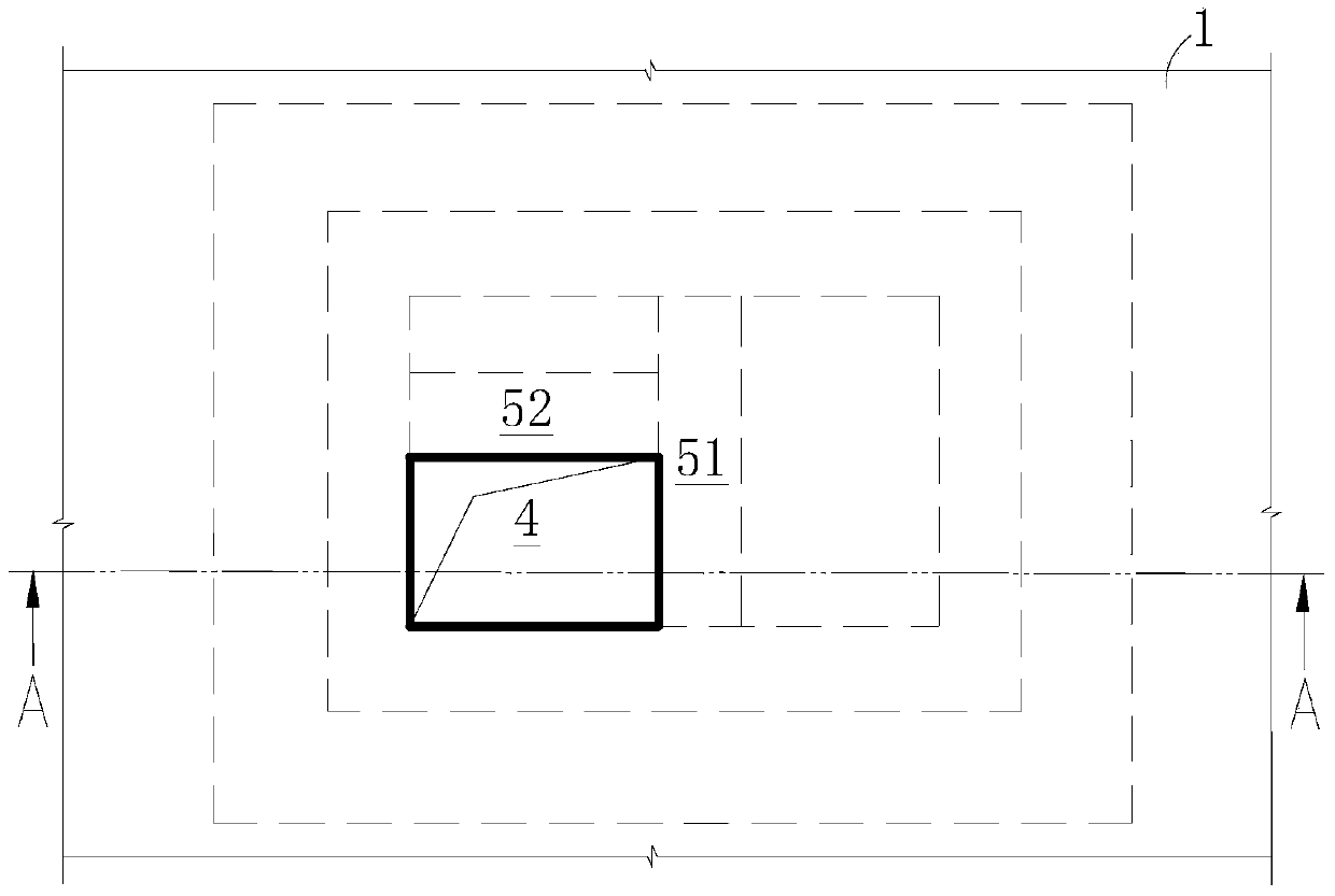
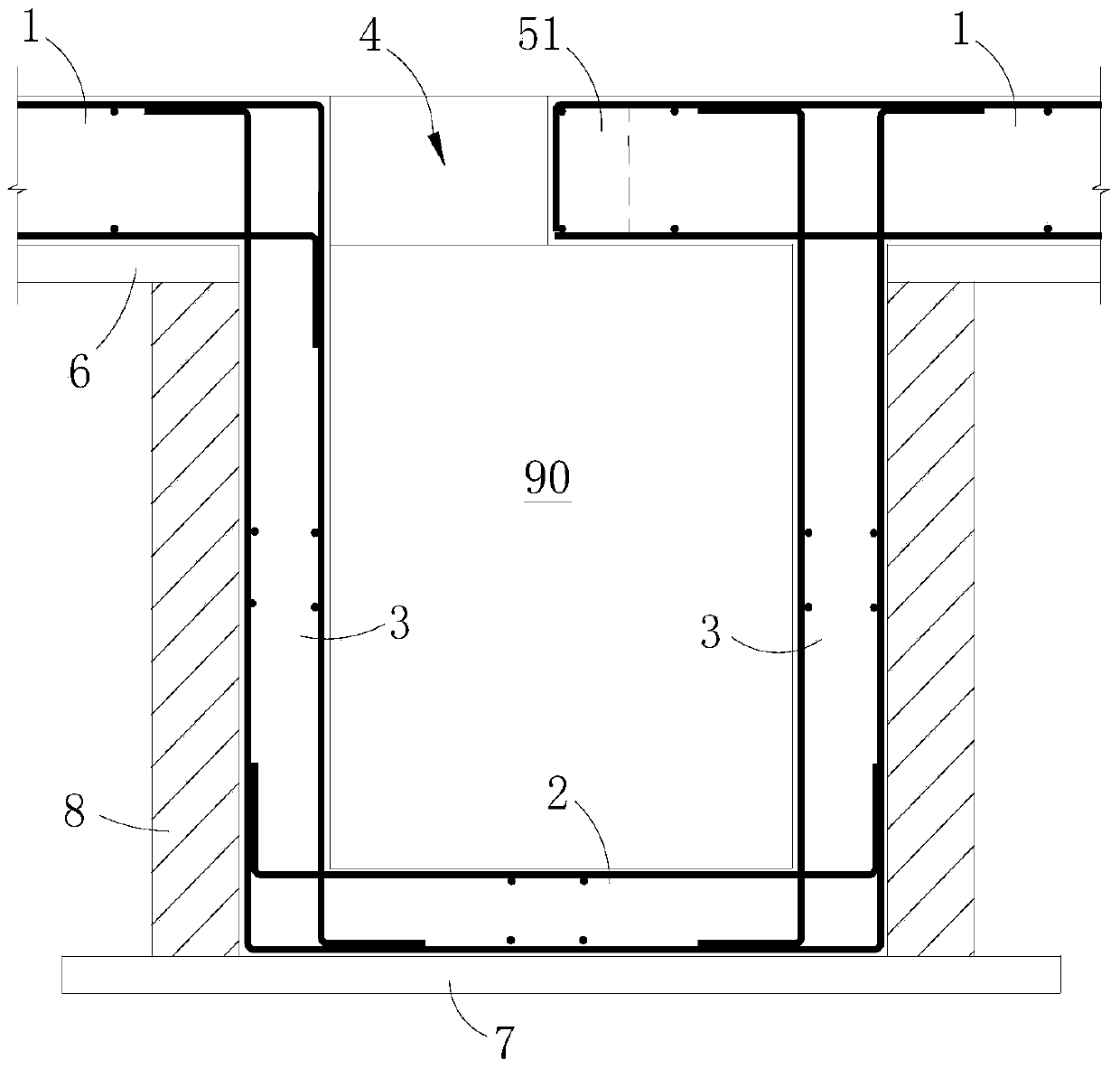
[0032] Such as Figure 1 to Figure 2 As shown, this embodiment is a basement sump structure, which is arranged under the basement floor 1 for temporarily storing sewage or miscellaneous water, and includes a sump main body fixed under the basement floor 1 . The sump main body includes a bottom plate 2 and a side wall 3 enclosing a sump chamber 90 . The water collecting cavity 90 is a cavity with an upper opening, the upper edge of the side wall 3 is fixedly connected to the basement floor 1, and the basement floor 1 is provided with a hole 4 at the opening above the water collecting cavity 90, and the area of ​​the hole 4 ( Size) is smaller than the area (size) of the opening of the sump cavity.

[0033]In the present invention, the dimension at the maximum width of the pit opening 4 is less than 1000 mm. In this embodiment, the pit mouth 4 is rectangular, and its size is less than or equal to 1000mm*1000mm. In order to further reduce the impact of the pit opening on the st...

Embodiment 2

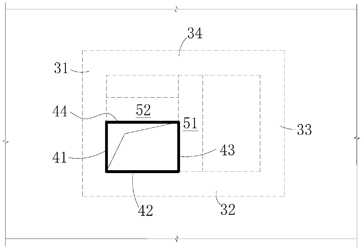
[0043] Such as Figure 4 As shown, the only difference between this embodiment and Embodiment 1 is that in this embodiment, the upper edge of the side wall 3 of the sump main body forms a circle, and the side wall 3 is formed by a vertical ring Constructed of reinforced concrete walls. The pit mouth 4 that the basement floor 1 opens at the opening above the water collection cavity is also circular in shape, the diameter of the pit mouth 4 is smaller than the diameter of the circle formed by the upper edge of the side wall 3, and the diameter of the pit mouth 4 is less than 1000mm, Specifically 700mm. In addition, two parallel supporting dark beams 51 and 52 are arranged in the basement floor part between the upper edge of the side wall 3 and the edge of the pit mouth 4. The two supporting dark beams are tangent to the pit mouth 4 and straddle the catchment The top of the main body of the pit is open and connected to two points on the upper edge of the side wall 3 .


PUM

PropertyMeasurementUnit
Sizeaaaaaaaaaa
Thicknessaaaaaaaaaa
Thicknessaaaaaaaaaa

Abstract

The invention relates to a basement sump structure. The basement sump structure is arranged below a bottom plate of a basement and used for temporarily storing sewage water or miscellaneous water. The basement sump structure comprises a sump body fixedly arranged below the bottom plate of the basement. The sump body comprises a bottom plate and sidewalls, wherein the bottom plate and the sidewalls define a catchment cavity. The catchment cavity is a cavity with an opening in the upper portion. The upper edges of the sidewalls are fixedly connected to the bottom plate of the basement. A pit opening communicated with the catchment cavity is formed in the position, located in the opening in the upper portion of the catchment cavity, of the bottom plate of the basement. The area of the pit opening is smaller than that of the opening of the catchment cavity. According to the basement sump structure, the pit opening formed in the bottom plate of the basement is shrunken, so that the size of the pit opening is smaller than that of the opening of the catchment cavity, and the influence of the formed pit opening on the structural rigidity and stability of the bottom plate of the basement is reduced.

Description

technical field [0001] The invention relates to the technical field of building waterproofing and drainage, in particular to a basement sump structure. Background technique [0002] In existing basement waterproof and drainage structures, sumps are often used to temporarily store sewage or miscellaneous water that needs to be discharged. The usual method is to open a large hole on the basement floor and set a sump in the hole. The side wall of the sump and the basement floor are connected by a steel bar with a bent structure, so the sump and the basement floor are integrated. Become an integral part of the basement floor, and the size of the sump area is the same as the size of the opening. [0003] There are several shortcomings in the above approach: [0004] (1) The force of the basement floor is interrupted, and the structural stability is weakened. As an integral part of the basement floor, the sump is set in the large hole opened in the basement floor, and the area ...

Claims


Application Information

Patent Timeline
IPC IPC(8): E03F5/10E04B1/00
Inventor 张继斌
Owner SHENZHEN GENERAL INST OF ARCHITECTURAL DESIGN & RES
Why Eureka
Try Eureka