
Method for carrying out construction in vertical shaft or inclined shaft through raise boring machine

A technology of a raise drilling rig and construction method, which is applied in drilling equipment and methods, drilling equipment, directional drilling and other directions, can solve the problems of high safety risks, twisted and broken drill pipes, and high deflection rate of pilot holes, and achieves increased economic benefits, The effect of speeding up the construction progress and ensuring the quality of the project

Inactive Publication Date: 2014-12-10
SINOHYDRO BUREAU 11 CO LTD
View PDF3 Cites 19 Cited by
  • Summary
  • Abstract
  • Description
  • Claims
  • Application Information

AI Technical Summary

Problems solved by technology

[0004] (1) High security risk;
[0005] (2) Long construction period and low efficiency;
[0006] (3) Over and under excavation is difficult to control;
[0007] (4) It is difficult to control the angle in the construction of the inclined shaft with gentle inclination angle
[0014] (6) Pay attention to the drilling speed during construction, and do not blindly pursue high footage, otherwise it is easy to cause high deflection rate of the pilot hole and it is difficult to control, and even twist the drill pipe

Method used


Image

  • Method for carrying out construction in vertical shaft or inclined shaft through raise boring machine

Examples


Embodiment 1

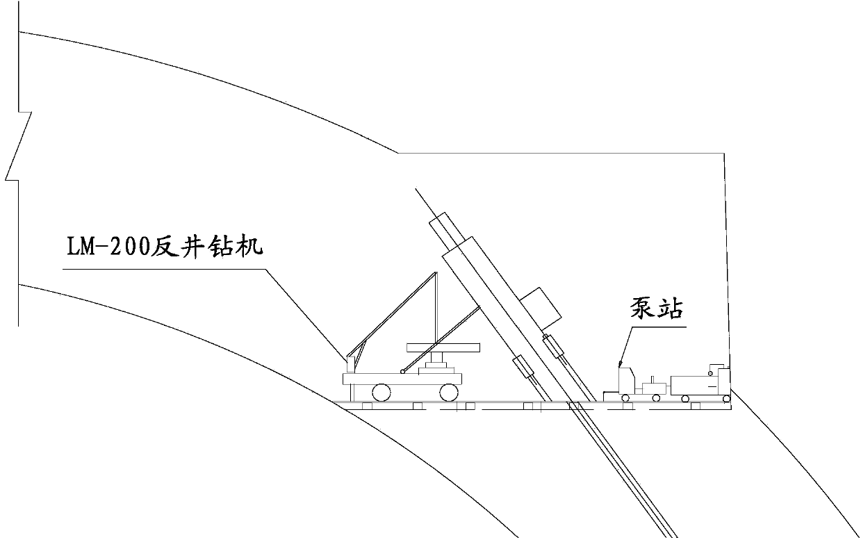
[0057] A method of using a raise drilling rig in underground well construction. The method uses the raising drilling rig to complete the construction of the guide well in the inclined well section. Drill a pilot hole with a diameter of Ф216mm in the downward direction. After the pilot hole is formed, replace the Ф216mm drill bit with a Ф1400mm expansion cutter in the downward bending section, and then form a slag guide well with a diameter of Ф1400mm by reverse pulling and expanding from bottom to top. The construction process is as follows:

[0058] Expansion and support of the upper bend section → construction of foundation and circulating water pool → cooling circulating water pool → installation and commissioning of raise drilling rig → pilot hole construction → reaming construction → drilling rig removal. The specific process of raising drilling rig construction is as follows:

[0059] 1. Pilot hole construction using Ф216mm pilot hole drill bit:

[0060] (1) The key to...


PUM

PropertyMeasurementUnit
Diameteraaaaaaaaaa

Abstract

The invention relates to a method for carrying out construction in a vertical shaft or an inclined shaft through a raise boring machine. The construction method comprises the steps that the raise boring machine is used for downwards drilling a guide hole with the diameter of 216 mm in an upper horizontal plane excavation expanding area of an upper curved section in the axis direction of the inclined shaft, a drill bit of phi216 mm is replaced with an excavation expanding tool disc of phi1,400 mm on a lower curved section after the guide hole is formed, and then a slip slug pilot shaft with the diameter phi of 1,400 mm is formed in a counter pull excavation expanding mode from top to bottom. According to the method for carrying out construction in the vertical shaft or the inclined shaft through the raise boring machine, construction and shaft guide are carried out by the raise boring machine in the hydropower project, and safety accidents are avoided in the construction process. Excavation and supporting of the vertical shaft and the slow inclined shaft are smoothly completed during the joint work period, the investment of personnel and equipment is reduced, the construction schedule is accelerated, meanwhile, project quality is guaranteed, and economic benefits are increased for the project. The experience measures for controlling angle deviation in the construction process of the vertical shaft and the slow inclined shaft are grasped, and reference is provided for controlling hole direction deviation through the raise boring machine in the construction process of the vertical shaft and the slow inclined shaft later.

Description

technical field [0001] The invention relates to a construction method for guiding wells in the excavation of vertical shafts and inclined shafts by adopting a raise drilling rig, and in particular relates to a construction technique that can completely replace the traditional manual reverse guiding shafts or climbing tank inclined shafts. Background technique [0002] Most hydropower stations are located in deep mountains and canyons, and their water diversion and power generation systems are mostly arranged underground. The layout of underground shafts and inclined shafts is very common. Vertical (inclined) shafts are not only long in length and large in diameter, but are often the most dangerous and difficult in the construction of the entire power station. , the construction project with the longest construction period and the most resource allocation, commonly known as the stuck neck project. The excavation of underground shafts and inclined shafts basically relies on th...

Claims


Application Information

Patent Timeline
IPC IPC(8): E21B7/00E21B7/04E21B7/28
Inventor 郭彦明卢代权潘大飞王世军许化栋王孝胜周瑞龚妇容凌卫军张卿陈卫华
Owner SINOHYDRO BUREAU 11 CO LTD
Learn More