Global calibration method for vision-guided camera of laser tracker

A laser tracker and vision-guided technology, applied in instruments, measuring devices, etc., can solve the problems of heavy workload, complex target processing, low precision, etc., and achieve the effect of improving efficiency, accurate calibration results, and simple operation

Inactive Publication Date: 2014-12-10
BEIHANG UNIV
View PDF7 Cites 22 Cited by
  • Summary
  • Abstract
  • Description
  • Claims
  • Application Information

AI Technical Summary

Problems solved by technology

[0008] However, the global calibration method of the traditional laser tracker vision guidance system requires complex target processing and low precision. During the calibration process, it is necessary to measure the coordinates of a large number of target feature points, and the workload is large. During the process of measuring target feature points The target is required to be fixed, and the spherical reflector needs to be in contact with the target during the measurement process, which will inevitably introduce certain errors

Method used


Image

  • Global calibration method for vision-guided camera of laser tracker
  • Global calibration method for vision-guided camera of laser tracker
  • Global calibration method for vision-guided camera of laser tracker

Examples


Embodiment Construction

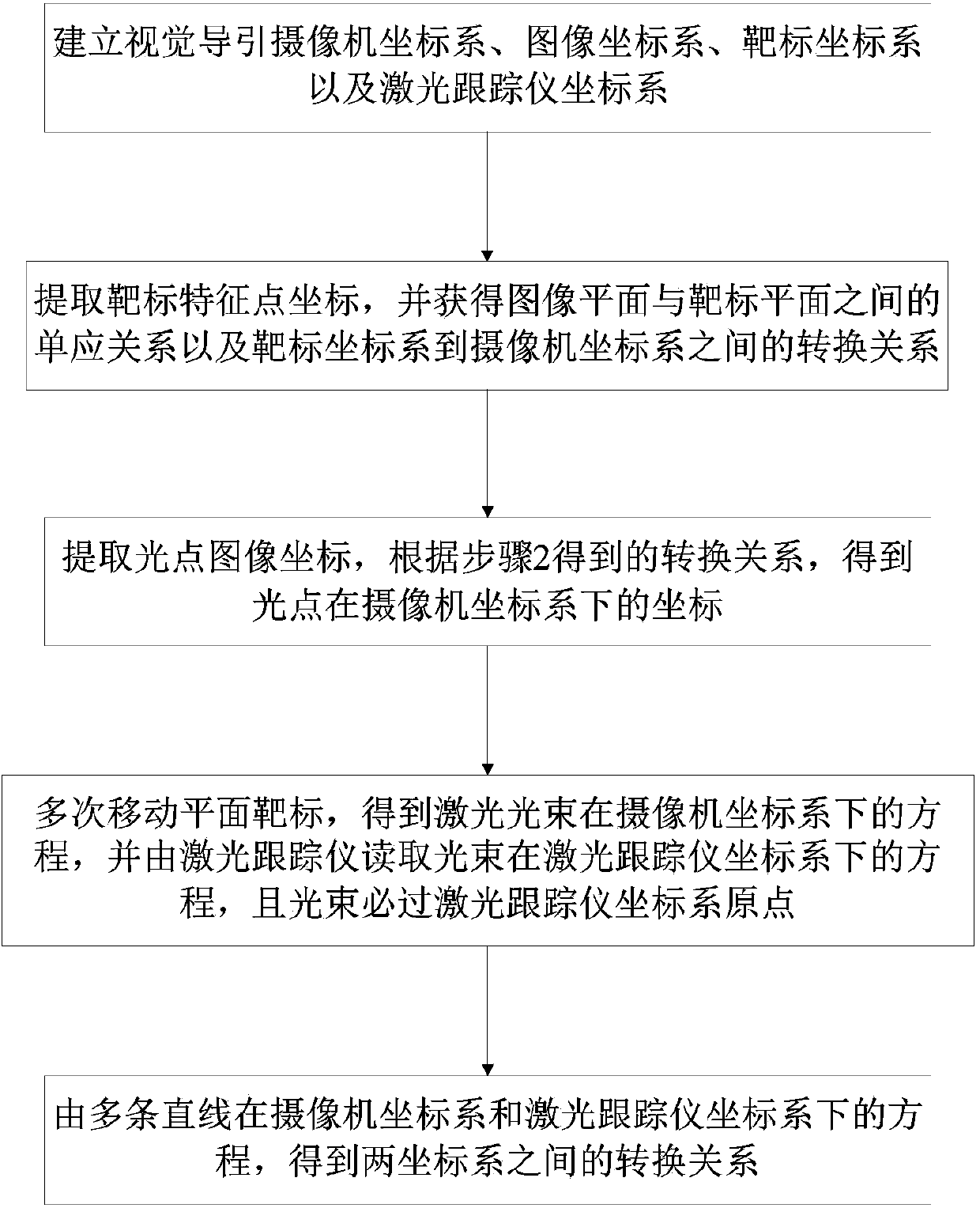
[0029] Such as figure 1 Shown, the inventive method realizes steps as follows:

[0030] 1. Establish camera coordinate system, image coordinate system, target coordinate system and laser tracker coordinate system.

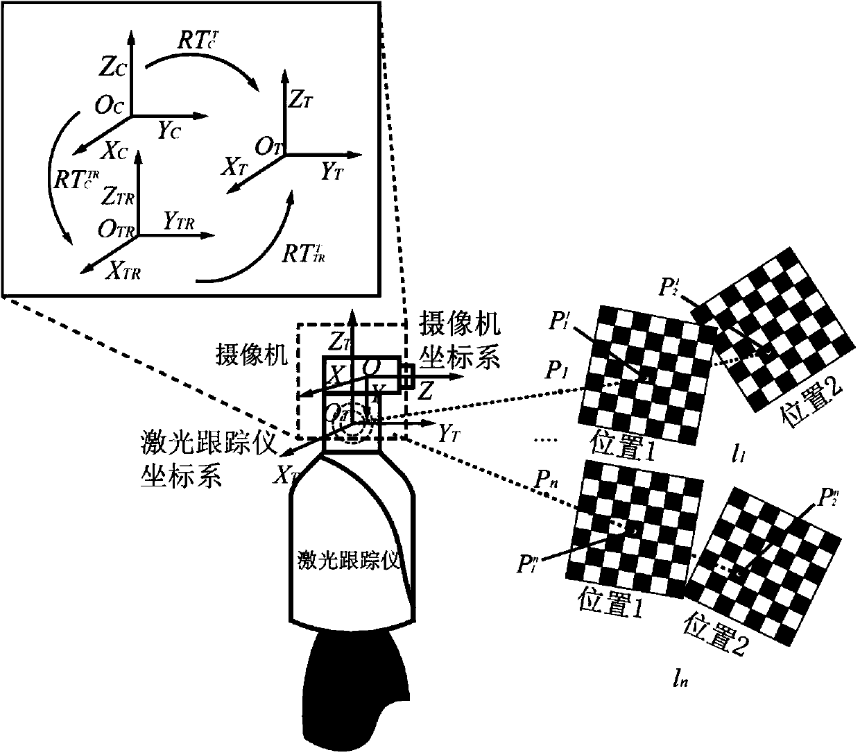
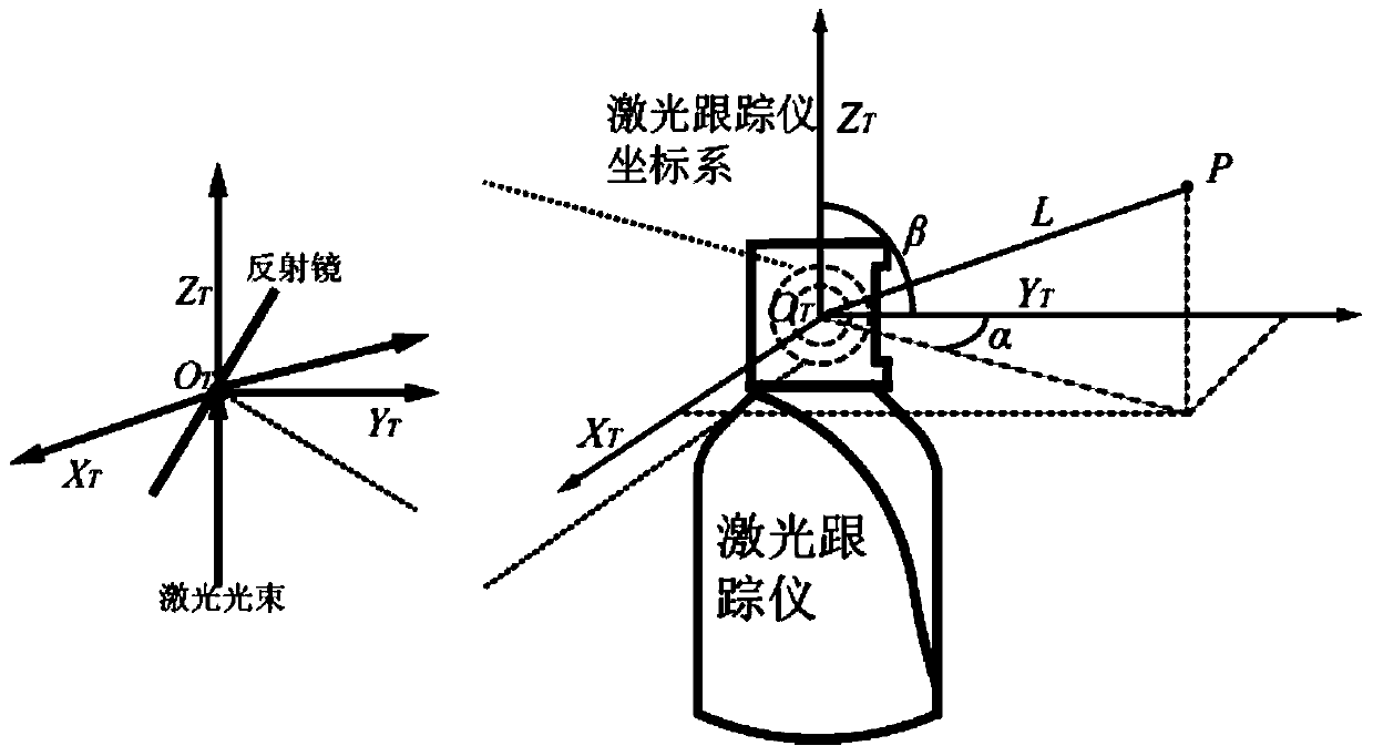
[0031] Such as figure 2 As shown, establish the camera coordinate system O C -X C Y C Z C , where O is the coordinate origin, XYZ is the direction of the three coordinate axes, the same below; the laser tracker coordinate system O T -X T Y T Z T , the target coordinate system O W -X W Y W Z W , the coordinate system of the laser tracker after rotation is O TR -X TR Y TR Z TR , is the coordinate system O W -X W Y W Z W to coordinate system O C -X CY C Z C the rotation matrix of is the coordinate system O W -X W Y W Z W to coordinate system O C -X C Y C Z C the translation matrix of is the camera coordinate system O C -X C Y C Z C to coordinate system O TR -X TR Y TR Z TR the rotation matrix of is the camera coordinate...


PUM


Abstract

The invention relates to a global calibration method for a vision-guided camera of a laser tracker. The method comprises the following steps: establishing a camera coordinate system, an image coordinate system, a laser tracker coordinate system and a target coordinate system; projecting a laser beam onto a plane target, and forming an image on the vision-guided camera, and repeatedly moving a target to obtain the linear equation of the laser beam in the camera coordinate system; obtaining laser tracker motion parameters, namely obtaining the linear equation of the laser beam in the laser tracker coordinate system; after the equations of multiple laser beams are obtained, obtaining a conversion relation between the camera coordinate system and the laser tracker coordinate system. The global calibration method disclosed by the invention is simple in operation, and can complete calibration by using one plane target, so that the speed of the global calibration is improved, and errors because calibration objects are repeatedly measured by a spherical reflector are avoided, so that calibration results are more accurate.

Description

technical field [0001] The invention relates to a laser tracker measurement technology, in particular to a global calibration method for a laser tracker visual guidance system. Background technique [0002] The precise measurement of spatial point position is widely used in pose measurement and quality inspection in the field of modern industrial manufacturing, especially in the field of large-scale workpiece manufacturing and assembly, such as heavy machinery manufacturing, aerospace manufacturing, automobile and ship manufacturing, etc. As a portable three-dimensional measurement system in the industrial measurement system, the laser tracker measurement system has a large range (measurement diameter up to 80m), high precision (μm level), high data acquisition rate (3000point / s), and quick installation. It is easy to operate and is widely used in the field of manufacturing and assembling large-sized workpieces. [0003] A laser tracker is a spherical coordinate measuring d...

Claims


Application Information

Patent Timeline
Patent Type & Authority Applications(China)
IPC IPC(8): G01C25/00
CPCG01C25/00
Inventor 魏振忠邵明伟张广军
Owner BEIHANG UNIV
Why Eureka
Try Eureka