A global calibration method for laser tracker vision-guided camera
A laser tracker, vision-guided technology
- Summary
- Abstract
- Description
- Claims
- Application Information
AI Technical Summary
Problems solved by technology
Method used
Image
Examples
Embodiment Construction
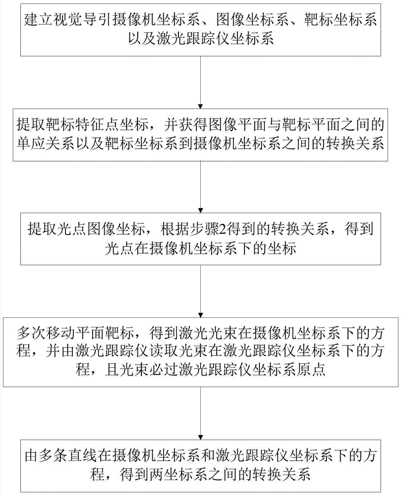
[0030] Such as figure 1 Shown, the inventive method realizes steps as follows:
[0031] 1. Establish camera coordinate system, image coordinate system, target coordinate system and laser tracker coordinate system.
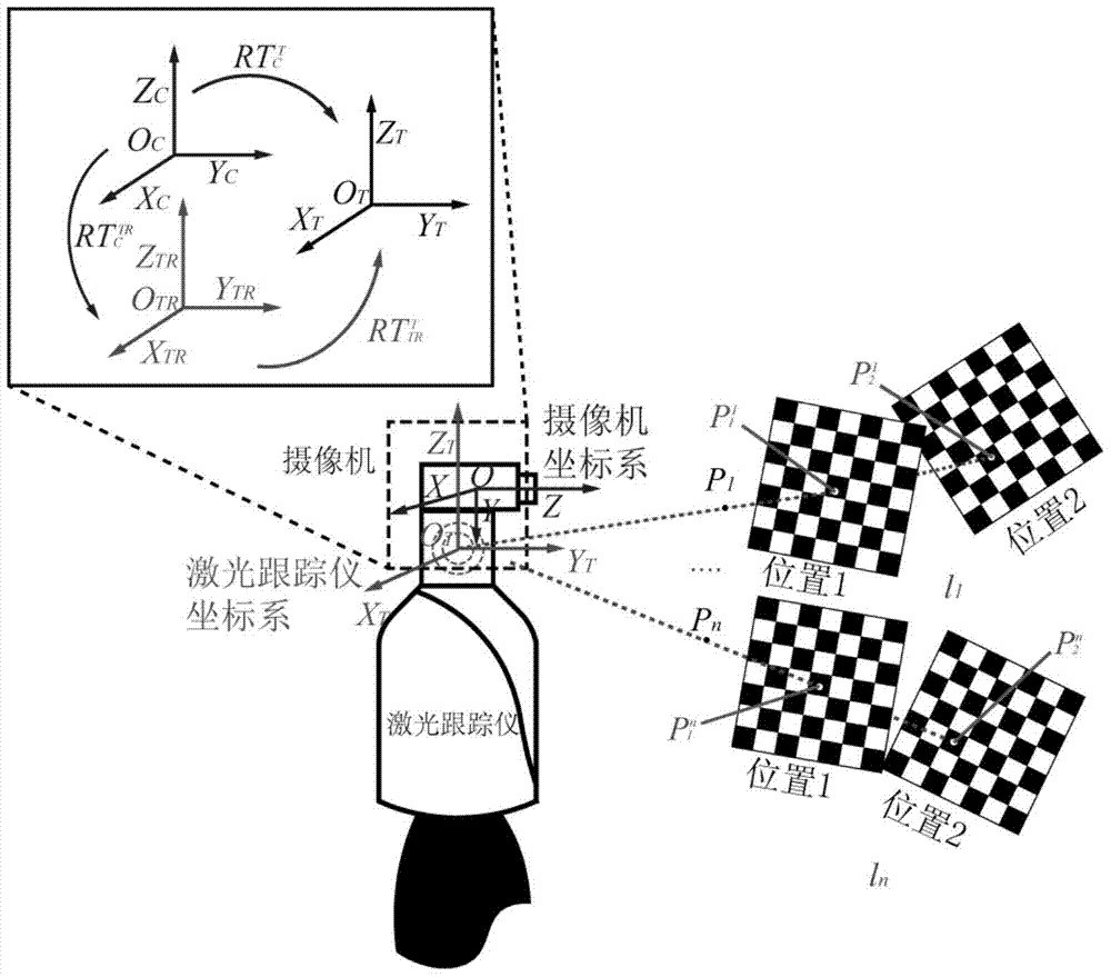
[0032] Such as figure 2 As shown, establish the camera coordinate system O C -X C Y C Z C , where O is the coordinate origin, XYZ is the direction of the three coordinate axes, the same below; the laser tracker coordinate system O T -X T Y T Z T , the target coordinate system O W -X W Y W Z W , the coordinate system of the laser tracker after rotation is O TR -X TR Y TR Z TR , is the coordinate system O W -X W Y W Z W to coordinate system O C-X C Y C Z C the rotation matrix of is the coordinate system O W -X W Y W Z W to coordinate system O C -X C Y C Z C the translation matrix of is the camera coordinate system O C -X C Y C Z C to coordinate system O TR -X TR Y TR Z TR the rotation matrix of is the camera coordinate...
PUM
 Abstract
Description
Claims
Application Information
 - R&D
- Intellectual Property
- Life Sciences
- Materials
- Tech Scout
- Unparalleled Data Quality
- Higher Quality Content
- 60% Fewer Hallucinations
Browse by: Latest US Patents, China's latest patents, Technical Efficacy Thesaurus, Application Domain, Technology Topic, Popular Technical Reports.
© 2025 PatSnap. All rights reserved.Legal|Privacy policy|Modern Slavery Act Transparency Statement|Sitemap|About US| Contact US: help@patsnap.com


