
Current waveform/rectangular pulse conversion circuit device

A rectangular pulse and conversion circuit technology, applied in the field of circuit devices, can solve the problems of high reliability, poor reliability, and difficulty in detecting the number of fundamental wave cycles, and achieve the effect of reliable counting and cost reduction

Inactive Publication Date: 2014-12-10
NINGBO SHUANGLIN AUTO PARTS
View PDF9 Cites 2 Cited by
  • Summary
  • Abstract
  • Description
  • Claims
  • Application Information

AI Technical Summary

Problems solved by technology

In the prior art, there are two types of conversion circuit devices used for counting the rotation angles of the driving motors of automobile windows, one is the current type, and the other is the Hall type; the so-called current type is generated by the rotation of the motor rotor by the waveform acquisition circuit 01 The current fluctuation is converted into a current waveform signal, and the current waveform signal is directly provided to the computer for rotation angle counting processing; due to the complex composition of the current waveform, DC components and higher harmonics above the second order are superimposed in the waveform, so the number of cycles of the fundamental wave is detected It is very difficult, resulting in a large error in corner counting, high error accumulation, and unreliable counting; the advantage of the current type is low cost, and the disadvantage is poor reliability; the so-called Hall type is a Hall brush with a Hall circuit inside. DC motor, referred to as Hall motor, converts the rotation angle of the rotor into a pulse square wave through the Hall circuit, and provides the pulse square wave to the computer through a special feeder for counting the rotation angle; the advantage of the Hall type is reliability High, the disadvantage is high cost; therefore, there are problems and deficiencies in the prior art such as high cost or poor reliability

Method used


Image

  • Current waveform/rectangular pulse conversion circuit device
  • Current waveform/rectangular pulse conversion circuit device
  • Current waveform/rectangular pulse conversion circuit device

Examples


Embodiment Construction

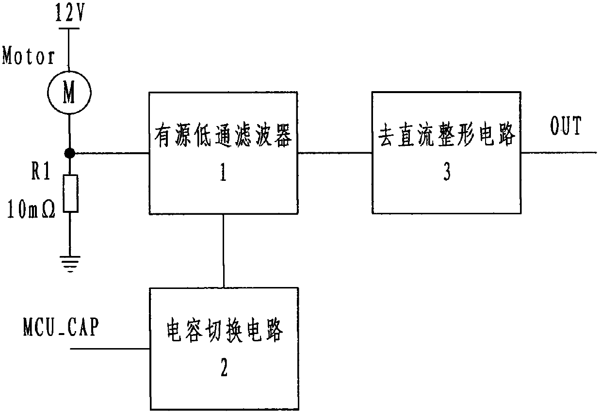
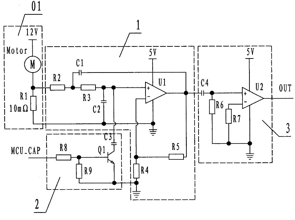
[0024] refer to Figure 1 to Figure 5 , a current waveform / rectangular pulse conversion circuit device of the present invention includes an active low-pass filter 1, a capacitor switching circuit 2 and a DC shaping circuit 3, wherein: the active low-pass filter 1 is composed of an operational amplifier Composed of U1, capacitor C1, capacitor C2, resistor R2, resistor R3, resistor R4, and resistor R5;

[0025] The capacitor switching circuit 2 is composed of a transistor Q1, a capacitor C3, a resistor R8, and a resistor R9;

[0026] The described DC shaping circuit 3 is composed of an operational amplifier U2, a capacitor C4, a resistor R6, and a resistor R7;

[0027] The upper end of the capacitor C3 of the capacitor switching circuit 2 is connected in parallel with the upper end of the capacitor C2 of the active low-pass filter 1; the output terminal of the operational amplifier U1 of the active low-pass filter 1 is connected with the DC shaping circuit 3 is connected to th...


PUM


Abstract

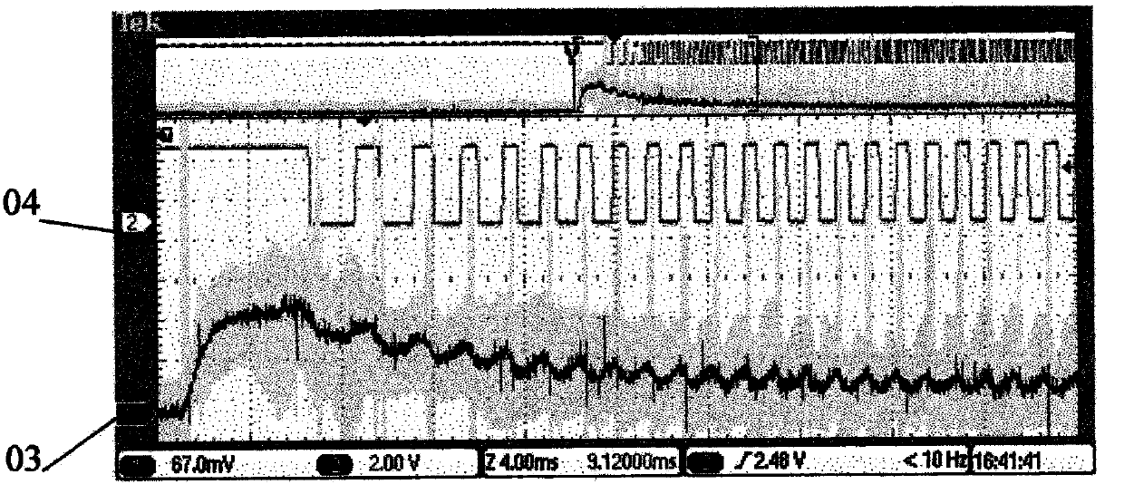
The invention discloses a current waveform / rectangular pulse conversion circuit device which comprises an active low-pass filter (1), a capacitor switching circuit (2) and a direct-current removing shaping circuit (3). When the circuit device works, the active low-pass filter is used for filtering more than secondary harmonic waves in a current waveform provided by a waveform acquisition circuit, the direct-current removing shaping circuit is used for removing direct-current components in the current waveform and shaping the current waveform into pulse square waves to be outputted, and the capacitor switching circuit is controlled by a computer and used for reducing or increasing the cut-off frequency of the active low-pass filter by switching on or off a capacitor C3 when a motor starts, stalls or runs at a constant speed to overcome the shortcoming that more than secondary harmonic waves run over degraded pulse square waves due to working change of the motor. By converting the current waveform into the pulse square waves, the conversion circuit device achieves the purposes of cost reduction and reliable counting.

Description

technical field [0001] The invention relates to a circuit device, specifically a current waveform / rectangle that collects the current fluctuation signal of the rotor of a brushed DC motor and processes it into a pulse square wave output for counting the number of rotations of the motor rotor. Pulse conversion circuit device. Background technique [0002] The car window uses a drive motor controlled by a computer to lift the glass. The drive motor for lifting the car window glass is a brushed DC motor, referred to as the motor; The danger of entrapment of hands, heads or other objects accidentally inserted, there have been reports of children being trapped by the closing glass because their heads were inserted into the window. For this reason, European and American standards stipulate that when the window glass automatically rises within 4 to 200 mm below the window frame, an object should be automatically lowered if it is clamped. The pressure on the clamped object, includi...

Claims


Application Information

Patent Timeline
IPC IPC(8): G01D5/244
Inventor 杜林新张帅涛李峰马健
Owner NINGBO SHUANGLIN AUTO PARTS
Learn More