Microwave correlated imaging method based on radar rotating emission array

A technology of transmitting array and imaging method, which is applied in the direction of using re-radiation, radio wave measurement system, and radio wave reflection/re-radiation, etc., can solve the problems of low degree of freedom, low resolution, and poor imaging effect of large scene targets.

Active Publication Date: 2014-12-10
XIDIAN UNIV
View PDF10 Cites 6 Cited by
  • Summary
  • Abstract
  • Description
  • Claims
  • Application Information

AI Technical Summary

Problems solved by technology

The existing radar microwave imaging technology has a low degree of freedom in the space-time random radiation field, poor imaging effect and low resolution for large scene targets

Method used


Image

  • Microwave correlated imaging method based on radar rotating emission array
  • Microwave correlated imaging method based on radar rotating emission array
  • Microwave correlated imaging method based on radar rotating emission array

Examples


Embodiment Construction

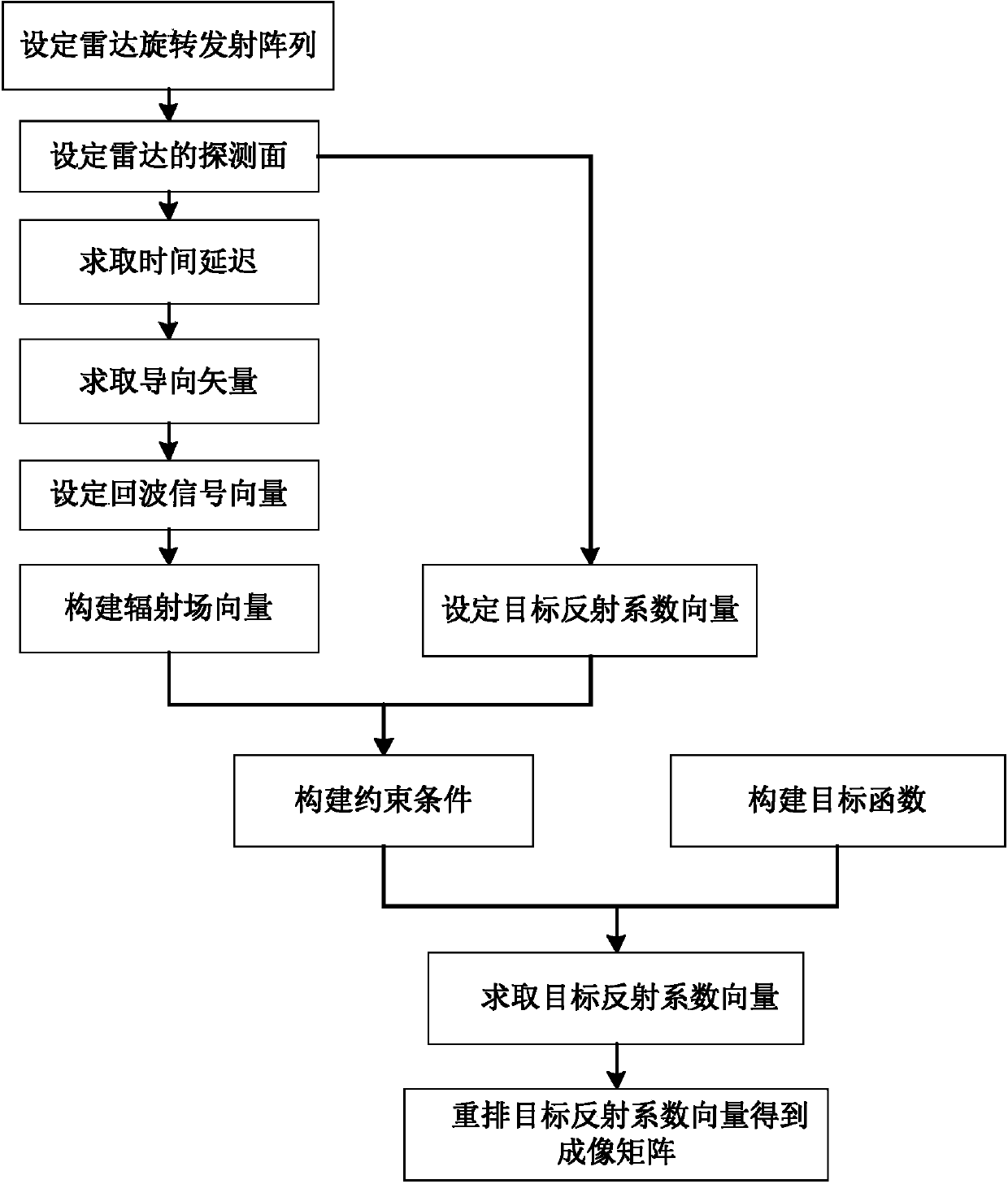
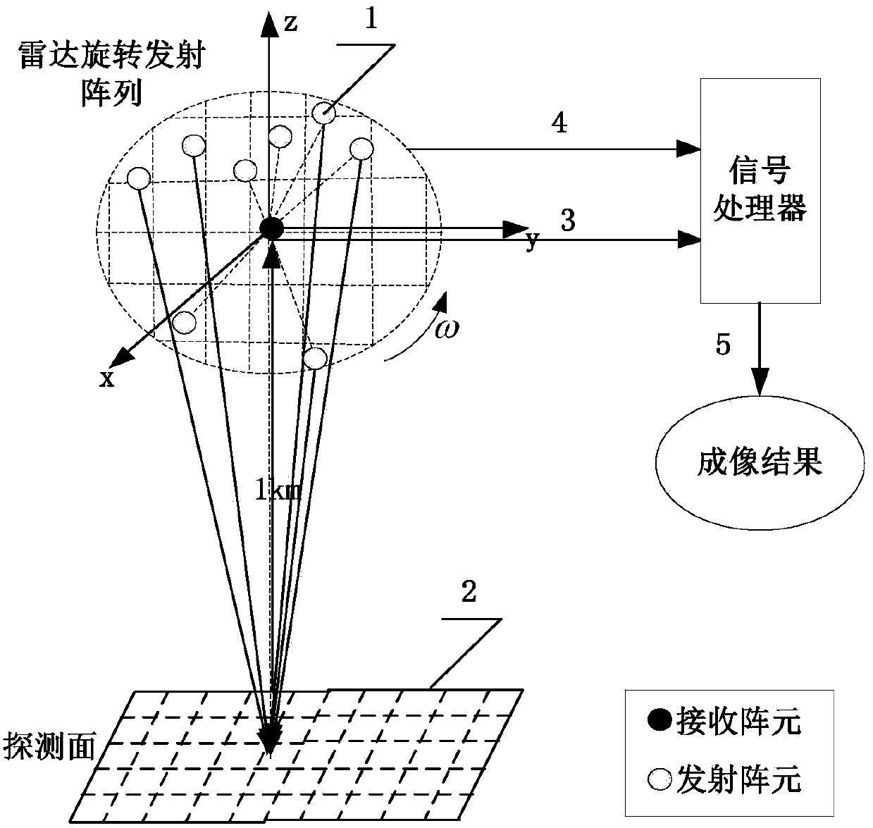
[0080] refer to figure 1 and figure 2 , which shows that the microwave correlation imaging method based on the radar rotating transmitting array of the present invention can be used in the structure of rotating transmitting array antenna, and realize the improvement of the randomness of the space-time random radiation field and the expansion of the degree of freedom.

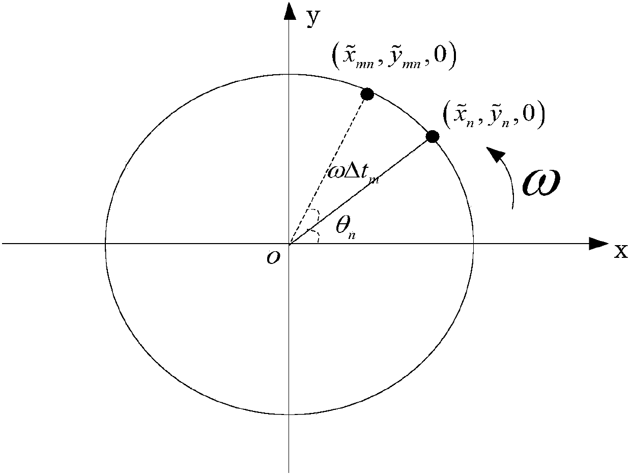
[0081] Step 1. The radar rotating transmitting array is a two-dimensional array with N array elements. The array elements of the radar rotating transmitting array are distributed on a circular surface. The radar receiver is located in the center of the circular surface, and the circular surface where the array elements are located bypasses The axis of the center of the circle rotates at an angular velocity ω, and the axis of the center of the circle is perpendicular to the circular surface.

[0082] Such as figure 2 shown. The radar rotating transmitting array is composed of transmitting array elements 1. T...


PUM


Abstract

The invention discloses a microwave correlated imaging method based on a radar rotating emission array and relates to the technical field of radar information acquisition and processing. The microwave correlated imaging method comprises the step 1 of setting a radar rotating emitting antenna, the step 2 of setting the detection surface of the radar and dividing the detection surface into a plurality of detection units, the step 3 of obtaining time delay, the step 4 of obtaining a steering vector by use of the time delay to obtain an array manifold matrix, the step 5 of setting an echo signal vector, the step 6 of establishing a radiation field vector, the step 7 of establishing the correlation form of an original echo vector under M pulses received by the radar and the radiation field vector, the step 8 of solving the objective function of an objection reflection coefficient vector under the constraint condition of the objective function to obtain the objection reflection coefficient vector, and the step 9 of obtaining a rearranged objection reflection coefficient vector matrix, namely the imaging matrix of an objection. The microwave correlated imaging method based on the radar rotating emission array is capable of improving the space-time randomness and the spatial freedom of the radiation field and realizing high resolution image of a large-scene objection.

Description

technical field [0001] The invention belongs to the technical field of radar information acquisition and processing, and relates to microwave correlation imaging technology, in particular to a microwave correlation imaging method based on a radar rotating transmitting array. technical background [0002] Correlation imaging has achieved rapid development in recent years. Correlation imaging is different from traditional radar imaging. Correlation imaging requires light sources to participate in the imaging process, and requires light sources to have statistical characteristics of heat and light, that is, randomness in time and space. fluctuation characteristics. In the actual experimental process, the method of pseudothermolight is generally used instead of real thermolight to study correlation imaging. Martienssen et al. proposed a method of pseudothermolight generation, that is, laser light is used to irradiate the rotating frosted glass, and pseudothermolight is generated...

Claims


Application Information

Patent Timeline
Patent Type & Authority Applications(China)
IPC IPC(8): G01S13/89G06F19/00G01S7/41
CPCG01S13/89G01S13/90G01S13/9082
Inventor 李军李小敏朱圣棋邵自立廖桂生吕利马玉芳
Owner XIDIAN UNIV
Why Eureka
Try Eureka