
A new type of multi-protection outdoor terminal box

A terminal box, multiple technologies, applied in the direction of substation/distribution device housing, electrical components, substation/switchgear cooling/ventilation, etc., can solve the problems of reduced insulation performance, great harm, burnout, etc., to ensure normal operation. , Complete dehumidification, prevent rust effect

Active Publication Date: 2016-06-29
STATE GRID CORP OF CHINA +1
View PDF6 Cites 0 Cited by
  • Summary
  • Abstract
  • Description
  • Claims
  • Application Information

AI Technical Summary

Problems solved by technology

[0002] At present, during the heating process of the heating and dehumidification system of the traditional terminal box, the surface temperature of the heater rises sharply, and the surrounding devices are greatly affected by the high temperature, and there is a potential risk of burning out
Due to the influence of the external temperature and the poor airtightness of the box, the power configuration of the heater is not easy to calculate from the time when the heater starts electric heating to the time when the overall air temperature inside the box reaches the required temperature; if the power is too small, the heating The fluid formed by the water vapor near the device will circulate in the relatively sealed box under the action of heat, which will accelerate the damp and rust of the terminal block and the aging of the cable sheath, reducing the insulation performance
In addition, for some terminal boxes without ventilation holes, simple electric heating can discharge part of the water vapor, but at the same time the heated water vapor rises and condenses into water droplets on the inner wall of the top of the terminal box. To the running terminal block, it will cause short circuit or grounding of the secondary circuit, and even cause malfunction of the circuit breaker, which is extremely harmful

Method used


Image

  • A new type of multi-protection outdoor terminal box
  • A new type of multi-protection outdoor terminal box
  • A new type of multi-protection outdoor terminal box

Examples


Embodiment Construction

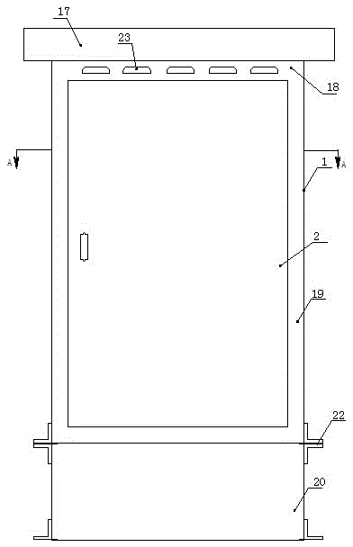
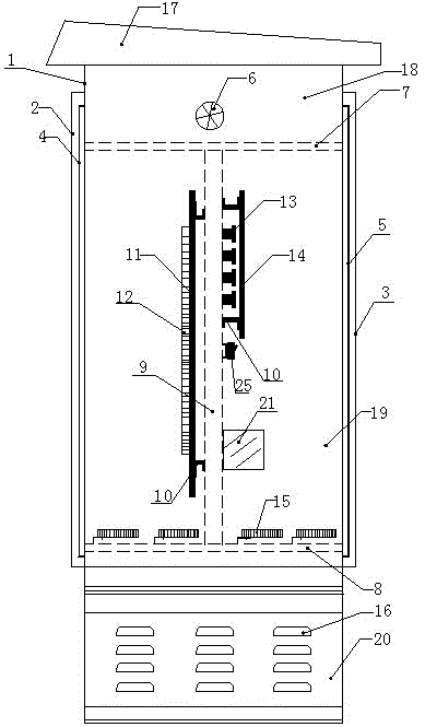
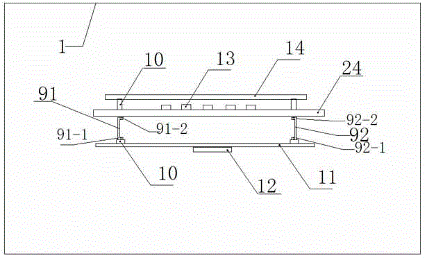
[0013] Such as figure 1 , 2 Shown in and 3, the present invention comprises cube-shaped box body 1, and box body 1 top is provided with roof shape rainproof cover 17, and box body 1 front and back are all provided with box door, are respectively front box door 2, rear box door 3 There are moisture-proof rubber rings 4 and 5 around the door frame of the box body 1. When the box door is closed, the inner edge of the box door is pressed tightly on the moisture-proof rubber ring to achieve the purpose of sealing and moisture insulation; the box body 1 The inner level is provided with a top mounting plate 7 and a bottom mounting plate 8. The top mounting plate 7 and the bottom mounting plate 8 divide the box body 1 into upper, middle and lower chambers. The upper chamber is a ventilation chamber 18, and the middle chamber It is a storage chamber 19, the lower chamber is a moisture isolation chamber 20, and multiple rows of mounting holes are provided on the top mounting plate 7 an...


PUM


Abstract

The invention discloses a novel multi-protection type outdoor terminal box, which comprises a box body with box doors at the front and rear, a top mounting plate and a bottom mounting plate horizontally arranged in the box body, which are divided into an upper ventilation chamber, a middle The storage chamber, the lower moisture isolation chamber, the door frame of the cabinet is surrounded by moisture-proof rubber rings, the top mounting plate and the bottom mounting plate are provided with multiple rows of mounting holes; A ventilator; two pillars arranged in parallel are arranged in the storage chamber, the top and bottom ends of the pillars are correspondingly connected to the mounting holes by bolts, the front end of the pillars is connected to the insulating board through the bracket, and the insulating board is provided with terminal blocks. The end face is connected to the slot plate, and the slot plate is equipped with low-voltage busbar and air switch. Low-power heater; heat dissipation holes are provided on the left and right walls of the box surrounding the moisture isolation chamber.

Description

technical field [0001] The invention relates to the technical field of outdoor terminal boxes, in particular to a novel multi-protection outdoor terminal box. Background technique [0002] At present, during the heating process of the heating and dehumidification system of the traditional terminal box, the surface temperature of the heater rises sharply, and the surrounding devices are greatly affected by the high temperature, and there is a potential risk of burning out. Due to the influence of the external temperature and the poor airtightness of the box, the power configuration of the heater is not easy to calculate from the time when the heater starts electric heating to the time when the overall air temperature inside the box reaches the required temperature; if the power is too small, the heating The fluid formed by the water vapor near the device will circulate in the relatively sealed box under the action of heat, which will accelerate the damp and rust of the termin...

Claims


Application Information

Patent Timeline
Patent Type & Authority Patents(China)
IPC IPC(8): H02B1/46H02B1/56H02B1/28
Inventor 赵新卫张绍通
Owner STATE GRID CORP OF CHINA
Learn More