An automatic control regenerative drainage system and its control method

A drainage system and automatic technology, applied in separation methods, ion exchange regeneration, chemical instruments and methods, etc., can solve the problems of small broken resin space, easy overload, affecting equipment and personnel safety, etc., to achieve convenient cleaning and filter flushing , Increase the service cycle and life, facilitate the effect of sinking and discharge

Active Publication Date: 2016-08-24
NANJING CEC ENVIRONMENTAL ENGINEERING CO LTD
View PDF5 Cites 0 Cited by
  • Summary
  • Abstract
  • Description
  • Claims
  • Application Information

AI Technical Summary

Problems solved by technology

[0005] The traditional horizontal pressurized wastewater resin trap has a small space for storing broken resin. When the regeneration system resin scrubs, flushes and rinses, when the amount of broken resin is large, it is easy to exceed the load of the small-diameter wastewater resin trap.
The traditional horizontal pressurized waste water resin trap has a horizontal structure. When the equipment is draining, some broken resin and other debris between the left end cover and the filter element installation ring cannot be completely drained.
It is not convenient to manually clean up the sundries and broken resin in the lower part of the filter element
The traditional atmospheric pressure wastewater resin trap has a high equipment height and a generally large diameter. After the resin is trapped, the resin recovery is inconvenient, and the equipment is not easy to clean thoroughly.
Because there is no differential pressure transmission device and no remote signal feedback, water often overflows from the upper end cover when the filter element is blocked during on-site operation, which greatly affects the safety of on-site equipment and personnel

Method used


Image

  • An automatic control regenerative drainage system and its control method
  • An automatic control regenerative drainage system and its control method
  • An automatic control regenerative drainage system and its control method

Examples


Embodiment Construction

[0030] The present invention will be further described below in conjunction with the accompanying drawings.

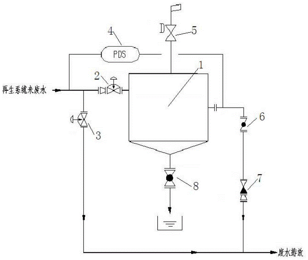
[0031] Such as figure 1 As shown, an automatic control regenerative drainage system includes a waste water resin trap 1, a water inlet valve 2 is arranged on the water inlet pipe of the waste water resin catcher 1, a bypass valve 3 is arranged on the water inlet bypass, and the caliber can be adjusted. The regeneration system is program-controlled and automatically interlocked to adapt to the continuous operation of the regeneration system. The outlet pipeline of the waste water resin trap 1 is provided with a normally open manual drain valve 6 and a check valve 7, and the water inlet bypass and the outlet pipe are connected to an external waste water discharge pipe. A normally open exhaust valve 5 is arranged on the top exhaust pipeline of the waste water resin trap 1 to facilitate the pressure relief of the equipment. A recovery valve 8 is installed at the bottom o...


PUM

PropertyMeasurementUnit
diameteraaaaaaaaaa

Abstract

The invention provides an automatic control regenerative drainage system, comprising a waste water resin catcher, a water inlet valve is arranged on the water inlet pipeline of the waste water resin catcher, a bypass valve is arranged on the water inlet bypass, the water inlet valve and the bypass The road valve is automatically interlocked and set; the outlet pipeline of the waste water resin catcher is provided with a normally open drain valve and a check valve, and the water inlet bypass and the water outlet pipe are connected to the external waste water discharge pipe; the waste water resin catcher A normally open exhaust valve is provided on the top exhaust pipeline, and a recovery valve is provided on the bottom resin recovery and sewage discharge pipeline; a differential pressure transmitter is provided between the water inlet and the water outlet of the waste water resin trap. The invention makes full use of the advantages of the automatic control regeneration drainage system and its core equipment, and the automatic control drainage system performs diversion interception and resin recovery according to the operation steps of the regeneration system and water quality types.

Description

technical field [0001] The invention relates to an automatic control regeneration drainage system and a control method thereof, and is a capture device for realizing zero discharge of resin and recovering good resin. Background technique [0002] With the development of my country's electric power industry, setting up condensate polishing has become a common trend. Ion exchange resins have been widely used in the field of finishing systems. The regeneration process of ion exchange resin is also demanding more and more, especially the regeneration drainage system needs reasonable improvement and innovation. An excellent regeneration drainage system can ensure the stable and continuous operation of the regeneration system, and can also improve the regeneration efficiency and resin recovery rate of the resin, so as to achieve the rationality of the regeneration drainage. [0003] The current regeneration drainage system is relatively simple, and the waste water discharged fro...

Claims


Application Information

Patent Timeline
Patent Type & Authority Patents(China)
IPC IPC(8): B01D29/48B01J49/85
CPCY02A20/402
Inventor 贺柏林王健张旭磊翁邵真
Owner NANJING CEC ENVIRONMENTAL ENGINEERING CO LTD
Why Eureka
Try Eureka