
Water closet with two groups of impellers and design scheme thereof

A design scheme and toilet technology, applied in the field of unpublished patent applications and PCT patent applications, can solve the problems of flushing potential energy waste and other problems, and achieve the effects of high water flow conversion rate, high conversion rate and resistance reduction.

Active Publication Date: 2014-12-17
唐山科理达环保科技有限公司
View PDF7 Cites 1 Cited by
  • Summary
  • Abstract
  • Description
  • Claims
  • Application Information

AI Technical Summary

Problems solved by technology

Compared with the technology of the present invention, the partial water flow control technology of toilet rotation and flushing proposed by me has the disadvantage of waste of flushing potential energy

Method used


Image

  • Water closet with two groups of impellers and design scheme thereof
  • Water closet with two groups of impellers and design scheme thereof
  • Water closet with two groups of impellers and design scheme thereof

Examples


Embodiment Construction

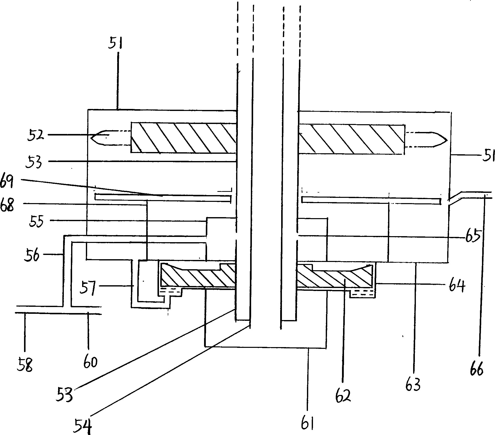
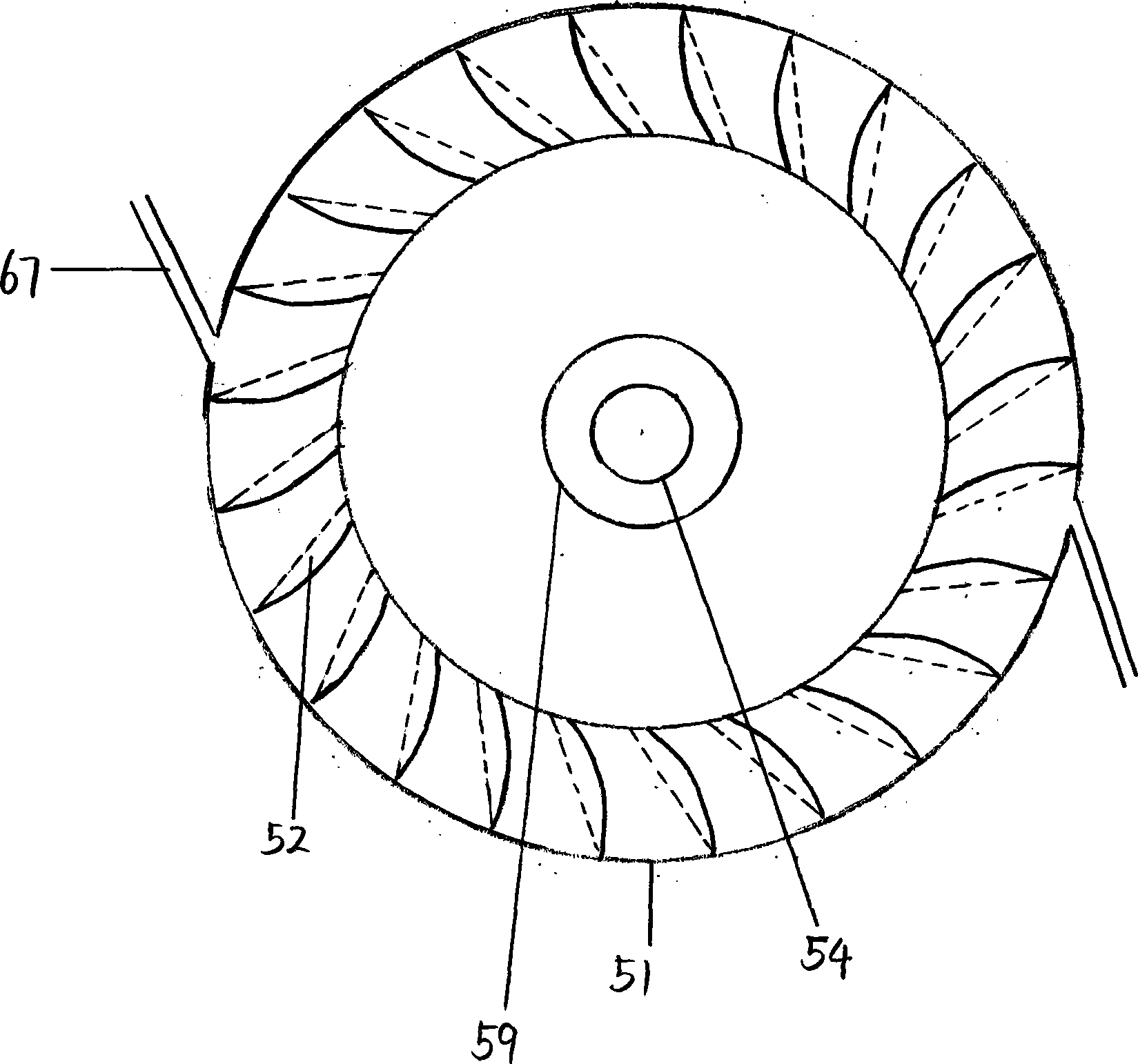
[0017] The type closet introduced for my above-mentioned patent application with the device now, the driving wheel (52) on the water spray shaft pipe of the device is bucket-shaped now, and the water repelling wheel (62) and its pump chamber (64) are DBZ type self-priming Taking the pump structure as an example, the device and design scheme of the present invention are introduced.

[0018] The closet spray shaft pipe (53) is sealed and surrounded by the container (51), the small container (55), the pump chamber (64), and the small container (61) from top to bottom respectively. Simultaneously, small container (55) is in large container (51), and the lower end (63) of large container (51) is also the lower end of small container (55), the upper end of pump chamber (64) simultaneously. The driving wheel (52) on the shaft tube (53) is located at the top of the container (51), and the shaft tube part surrounded by the small container (55) has a water inlet hole (65) on the shaft t...


PUM


Abstract

The invention provides a water closet with two groups of impellers and a design scheme thereof, discloses a water closet part rotating device, a water pressure control device and design schemes thereof, and relates to the technical field of water-saving water closets. The water closet is characterized in that in a container chamber (5) in which rotary impellers are arranged, the surrounding space outside the upper ends of the impellers is larger, and the tail water surface is enabled to be away from the impellers, so the drag of the impellers in the rotating process is reduced; a water pushing impeller (62) is arranged under the impellers (52), the periphery of the water pushing impeller is provided with a pump chamber (64), and the non-pressure tail water can be changed into the pressure spraying water by the water pushing impeller; an overflow passage (66) is arranged in the container (51) in which the driving impellers are arranged. The design scheme has the advantages that while the high-pressure water flow is changed into the non-pressure tail water, the non-pressure tail water is changed into the water flow with certain pressure; the feature of overcoming the bias of science and technology is realized.

Description

technical field [0001] The present invention relates to the technical field of water-saving toilet applications, especially the domestic patent application with the patent application number of 201210322706.0 and the PCT patent application with the patent number of PCT / CN2013 / 001035. In addition, it also involves several unpublished patent applications applied by the applicant. patent application. Background technique [0002] Most of the closets at present, except the novel closet that I apply for, hardly relate to the device technical scheme of the present invention. Compared with the technology of the present invention, the partial water flow control technology of toilet rotation and flushing proposed by me has the disadvantage of waste of flushing potential energy. Contents of the invention [0003] The invention mainly improves the device and scheme of the impeller which drives the rotation of the toilet piston and the water spray shaft tube and its structure, as wel...

Claims


Application Information

Patent Timeline
Patent Type & Authority Applications(China)
IPC IPC(8): E03D9/16
Inventor 王永强
Owner 唐山科理达环保科技有限公司
Learn More