
Manifold truck and its hydraulic control system

A technology of hydraulic control system and manifold truck, which is applied in the direction of fluid pressure actuators, servo motors, mechanical equipment, etc., and can solve the problems of many components, high energy consumption, and complex structure

Active Publication Date: 2016-08-31
SANY PETROLEUM INTELLIGENT EQUIP CO LTD
View PDF8 Cites 0 Cited by
  • Summary
  • Abstract
  • Description
  • Claims
  • Application Information

AI Technical Summary

Problems solved by technology

[0004] As we all know, generally speaking, the larger the space for arranging various manifold parts on the chassis of the manifold truck, the better, so the space occupied by other components is relatively limited, but in the hydraulic control system of the above-mentioned manifold truck, There are many components required, the structure is complex, the space occupied is large, the cost is high, the energy consumption is high, and each part is relatively independent, which makes it inconvenient to arrange and maintain, and it is not convenient for centralized coordination and control; in addition, the existing perfusion method is comparatively Single, it is difficult to adapt to the perfusion needs of manifold systems of different scales, and the process of pressure testing through plunger pumps is also inconvenient and complicated

Method used


Image

  • Manifold truck and its hydraulic control system

Examples


Embodiment Construction

[0051] It should be pointed out that the description and sequence of specific structures in this section are only descriptions of specific embodiments, and should not be considered as limiting the protection scope of the present invention. In addition, the embodiments in this section and the features in the embodiments can be combined with each other under the condition of no conflict.

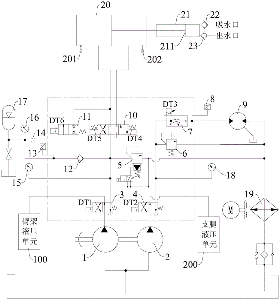
[0052] Please refer to figure 1 , the hydraulic control system of the manifold truck according to the embodiment of the present invention will be described in detail below in conjunction with the accompanying drawings.

[0053] As shown in the figure, the hydraulic control system of the manifold truck in this embodiment may include a boom pump 1, an outrigger pump 2, an outrigger hydraulic unit 200, a boom hydraulic unit 100, a first reversing valve 3, a second reversing valve Valve 4, pressure test main valve 10, oil cylinder 20, booster cylinder 21, speed regulating valve 7, filling motor 9...


PUM


Abstract

The invention discloses a manifold car and its hydraulic control system. In the present invention, the first reversing valve is used to connect the oil outlet of the boom pump to the oil inlet of the boom hydraulic unit, or to connect to one of the pressure test main valve and the oil inlet of the filling motor; The two reversing valves are used to connect the oil outlet of the outrigger pump to the oil inlet of the outrigger hydraulic unit, or to the other of the pressure test main valve and the oil inlet of the filling motor; the two ports of the pressure test main valve The two working oil ports are respectively connected to the rodless cavity and the rod cavity of the oil cylinder, and the oil return port of the pressure test main valve is connected to the oil return circuit. The pressure test main valve is used to realize the telescopic reversing or locking of the oil cylinder; The extended end of the piston rod is provided with a plug body, which is movably arranged in the pressurized cylinder, and the rodless chamber of the pressurized cylinder is connected with a suction valve and a discharge valve; the oil outlet of the filling motor is connected to the oil return circuit. The implementation of the present invention not only saves occupied space, is energy-saving and economical, but also is easy to arrange and maintain, and facilitates centralized coordinated control.

Description

technical field [0001] The invention relates to the technical field of manifold trucks, in particular to a manifold truck and its hydraulic control system. Background technique [0002] In fracturing construction operations, a manifold truck is often used, which is usually composed of a chassis, a truck-mounted hoisting system (including the boom part and outrigger part), an irrigation system (including an irrigation pump and an irrigation motor), a pressure test The system (including the pressure test pump) and various manifold components, etc., the manifold components generally include high and low pressure manifolds and high and low pressure fittings, high pressure fitting racks, high pressure fitting boxes, low pressure fitting boxes, etc. During use, after the manifold truck arrives at the site, various manifold components can be hoisted and unloaded to the ground through its on-board hoisting system. After the manifold components are assembled to form a manifold system...

Claims


Application Information

Patent Timeline
Patent Type & Authority Patents(China)
IPC IPC(8): F15B1/02F15B11/17F15B11/042
Inventor 张志强杨鑫周诗纬
Owner SANY PETROLEUM INTELLIGENT EQUIP CO LTD
Learn More