Optical system of particle analyzer

Pending Publication Date: 2014-12-17
SHENZHEN MINDRAY BIO MEDICAL ELECTRONICS CO LTD
View PDF7 Cites 17 Cited by
  • Summary
  • Abstract
  • Description
  • Claims
  • Application Information

AI Technical Summary

Problems solved by technology

However, the scattered light collection lens of the currently commonly used optical system is limited by the numerical aperture (NA), and the upper limit of the scattering angle

Method used


Image

  • Optical system of particle analyzer
  • Optical system of particle analyzer
  • Optical system of particle analyzer

Examples


Embodiment Construction

[0042] The present application will be described in further detail below through specific implementation manners and in conjunction with the accompanying drawings.

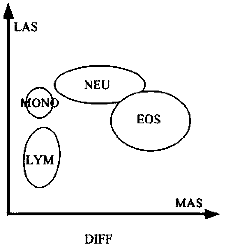
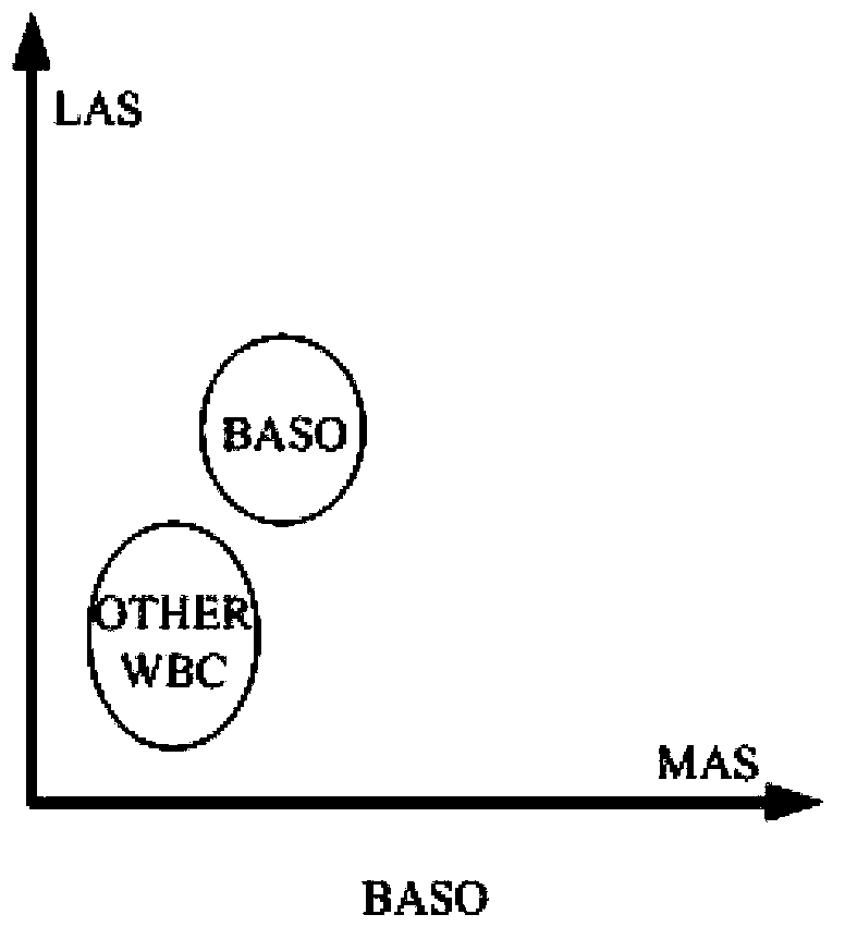
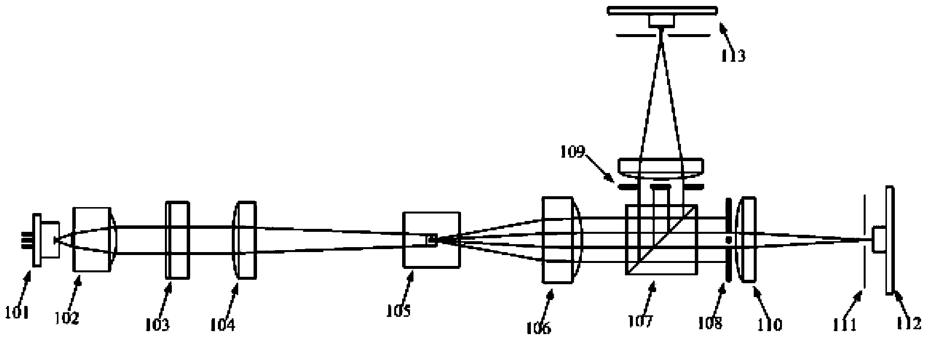
[0043]The particles to be measured emit scattered light after being excited by the light beam. In the embodiment of the present application, the scattered light in three angle ranges is collected, wherein the third angle range is larger than the second angle range, and the second angle range is larger than the first angle range, that is, the first The scattered light in the first angle range is low-angle scattered light, the scattered light in the second angle range is medium-angle scattered light, and the scattered light in the third angle range is large-angle scattered light. The intervals are not necessarily required to be continuous, but can have intervals of set angles, for example, the first angle range is 0°-8°, the second angle range is 10°-20°, and the third angle range is 23°-40° . In the embodiment of ...


PUM


Abstract

A disclosed optical system of a particle analyzer comprises a front light assembly, a flow chamber and a diffusion light collection assembly; the diffusion light collection assembly comprises a low-angle diaphragm, a low-angle photoelectric induction apparatus, a medium-angle diaphragm, a medium-angle photoelectric induction apparatus, a large-angle diaphragm and a large-angle photoelectric induction apparatus. On the detection basis of a conventional particle analyzer on low/medium-angle scope data particles, a diffusion light collection apparatus for detection of large-angle scope data particles is increased, so that detection on low/medium/large-angle scope data particles is realized, and three-dimensional data of a measured particle is obtained, and by collecting the diffusion light at a large-angle scope, more particle information can be obtained, and the particle classification accuracy is improved.

Description

technical field [0001] The present application relates to particle analyzers for particle identification using light scattering methods, and more particularly to optical systems for particle analyzers. Background technique [0002] Whether in the clinical field or the scientific research field, the automatic detection of the classification of tiny particles such as cells has great application value. For example, a blood cell analyzer as a particle analyzer can output red blood cells, white blood cells and The number and volume of platelets and other information. [0003] According to the different principles of particle detection and counting, particle classification methods can generally be divided into impedance method and light scattering method. [0004] The impedance method is based on Coulter's principle. Taking a blood cell analyzer as an example, the instrument analyzes and counts blood cells by measuring the impedance change on the electrodes at both ends of the sm...

Claims


Application Information

Patent Timeline
IPC IPC(8): G01N15/14G01N21/47
Inventor 孙尧陈旺富邵汉荣
Owner SHENZHEN MINDRAY BIO MEDICAL ELECTRONICS CO LTD
Why Eureka
Try Eureka