Liquid crystal display device

A technology for liquid crystal display devices and liquid crystal layers, applied in light guides, optics, instruments, etc., can solve the problems of decreased light output efficiency of backlight modules, increased cost of backlight modules, and decreased light transmittance, so as to improve light transmittance Comparing with the light output efficiency, solving the problem of large viewing angle deviation, and improving the effect of light penetration

Inactive Publication Date: 2014-12-17
TCL CHINA STAR OPTOELECTRONICS TECH CO LTD
View PDF7 Cites 9 Cited by
  • Summary
  • Abstract
  • Description
  • Claims
  • Application Information

AI Technical Summary

Problems solved by technology

VA mode has the advantages of high yield and high productivity, but in order to reduce the chromatic aberration displayed by large viewing angles, ITO electrodes must use 8domain patterns to improve large viewing angle deviation, but the use of 8domain patterns for ITO electrodes will reduce the process yield and aperture ratio. , the efficiency of liquid crystal decreases, and the light transmittance decreases, which indirectly increases the cost of the backlight module
If the 2domain or 1domain VA mode solution is used, the light penetration rate can be greatly improved, but the large-view role deviation will obviously become serious
[0007] In addition, because the display panel of the LCD TV needs to be viewed from a large viewing angle, the viewing angle brightness must meet the viewing angle specification requirements of 1 / 2 brightness or 1 / 3 brightness, and the optical film set of the backlight module needs to achieve a larger light emitting viewing angle, while the LCD panel The penetrability of light with a large viewing angle decreases, which reduces the light output efficiency of the backlight module, and makes the problem of large viewing angle deviation of the LCD panel obvious

Method used


Image

  • Liquid crystal display device
  • Liquid crystal display device
  • Liquid crystal display device

Examples


Embodiment Construction

[0027] In order to further illustrate the technical means adopted by the present invention and its effects, the following describes in detail in conjunction with preferred embodiments of the present invention and accompanying drawings.

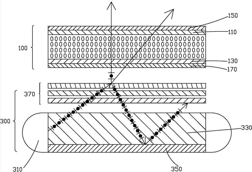
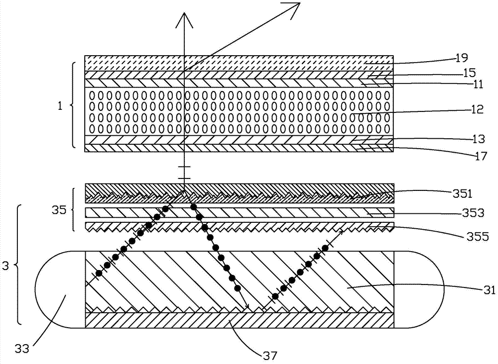
[0028] see figure 2 The present invention provides a liquid crystal display device, including a liquid crystal panel 1 and a collimated light-emitting backlight module 3 that provides a light source for the liquid crystal panel 1 .

[0029] The liquid crystal panel 1 includes a color filter substrate 11 , an array substrate 13 opposite to the color filter substrate 11 , and a liquid crystal layer 12 filled between the color filter substrate 11 and the array substrate 13 . The upper surface of the color filter substrate 11 relatively away from the liquid crystal layer 12 is attached with an upper polarizer 15 , and the lower surface relatively close to the liquid crystal layer 12 is provided with a color photoresist in units of pixels. A lowe...


PUM


Abstract

The invention provides a liquid crystal display device which comprises a liquid crystal panel (1) and a collimating emergent backlight module (3). The liquid crystal panel (1) comprises a color filter substrate (11), an array substrate (13) and a liquid crystal layer (12), an upper polarizer (15) is arranged on the upper surface of the color filter substrate (11), a lower polarizer (17) is arranged on the lower surface of the array substrate (13), the collimating emergent backlight module (3) comprises a light guide plate (31), at least one backlight source (33), an optical film group (35) and a bottom reflector plate (37), a visual angle diffusion film (19) is arranged on the upper polarizer (15), and the optical film group (35) comprises a birefringent polarization film (351) capable of separating polarized light. By the aid of the liquid crystal display device, light penetration rate and light extraction efficiency can be greatly increased, and the problem of large visual angle color offset can be effectively solved.

Description

technical field [0001] The invention relates to the technical field of liquid crystal display, in particular to a liquid crystal display device. Background technique [0002] Liquid Crystal Display (LCD) has many advantages such as thin body, power saving, and no radiation, and has been widely used, such as LCD TV, mobile phone, personal digital assistant, digital camera, computer screen or notebook computer screen Wait. [0003] Most of the existing liquid crystal display devices are backlight liquid crystal display devices, which include a housing, a liquid crystal panel disposed in the housing, and a backlight module disposed in the housing. The LCD panel itself does not emit light, and the backlight module needs to provide a light source for the LCD panel to display images normally. [0004] figure 1 Shown is a schematic diagram of a conventional liquid crystal display device. The structure of the traditional liquid crystal panel 100 is composed of a color filter sub...

Claims


Application Information

Patent Timeline
Patent Type & Authority Applications(China)
IPC IPC(8): G02F1/13357
CPCG02B6/0038G02B6/0053G02B6/0055G02B6/0056G02F1/133504G02F1/13362G02F1/133514G02F1/133528
Inventor 连水池康志聪郭仪正
Owner TCL CHINA STAR OPTOELECTRONICS TECH CO LTD
Why Eureka
Try Eureka