Simulation design method for rolling hole patterns of steel rail
What is AI technical title?
AI technical title is built by Patsnap AI team. It summarizes the technical point description of the patent document.
A technology of simulation design and pass design, applied in computing, special data processing applications, instruments, etc., can solve the problems of roll processing errors, high labor intensity, scrap rolls, etc., to avoid errors, reduce labor intensity, and improve accuracy. Effect
Active Publication Date: 2014-12-17
PANGANG GRP PANZHIHUA STEEL & VANADIUM
View PDF2 Cites 23 Cited by
Summary
Abstract
Description
Claims
Application Information
AI Technical Summary
This helps you quickly interpret patents by identifying the three key elements:
Problems solved by technology
Method used
Benefits of technology
Problems solved by technology
Not only is the labor intensity high, but the main problem is that there are many errors caused by manual writing and input. Roll processing errors often occur, and re-turning or even roll scrapping results in losses ranging from 100,000 to 1 million yuan.
Method used
Image
Click on the blue label to locate the original text in one second.
Reading with bidirectional positioning of images and text.
Examples
Embodiment 1
[0026] On the basis of the secondary development module of AutoCAD, the whole process of realizing the background sub-network operation without manual operation by using the bottom layer to call ANSYS pre-processing is as follows,
[0027] (1) First, according to the position of each key point calculated by the secondary development module of AutoCAD, a file recognizable by ANSYS is generated, and its implementation code is:
[0074] Taking a certain H-shaped steel BD1 roll matching as an example, the whole process of realizing the CAM module is introduced.
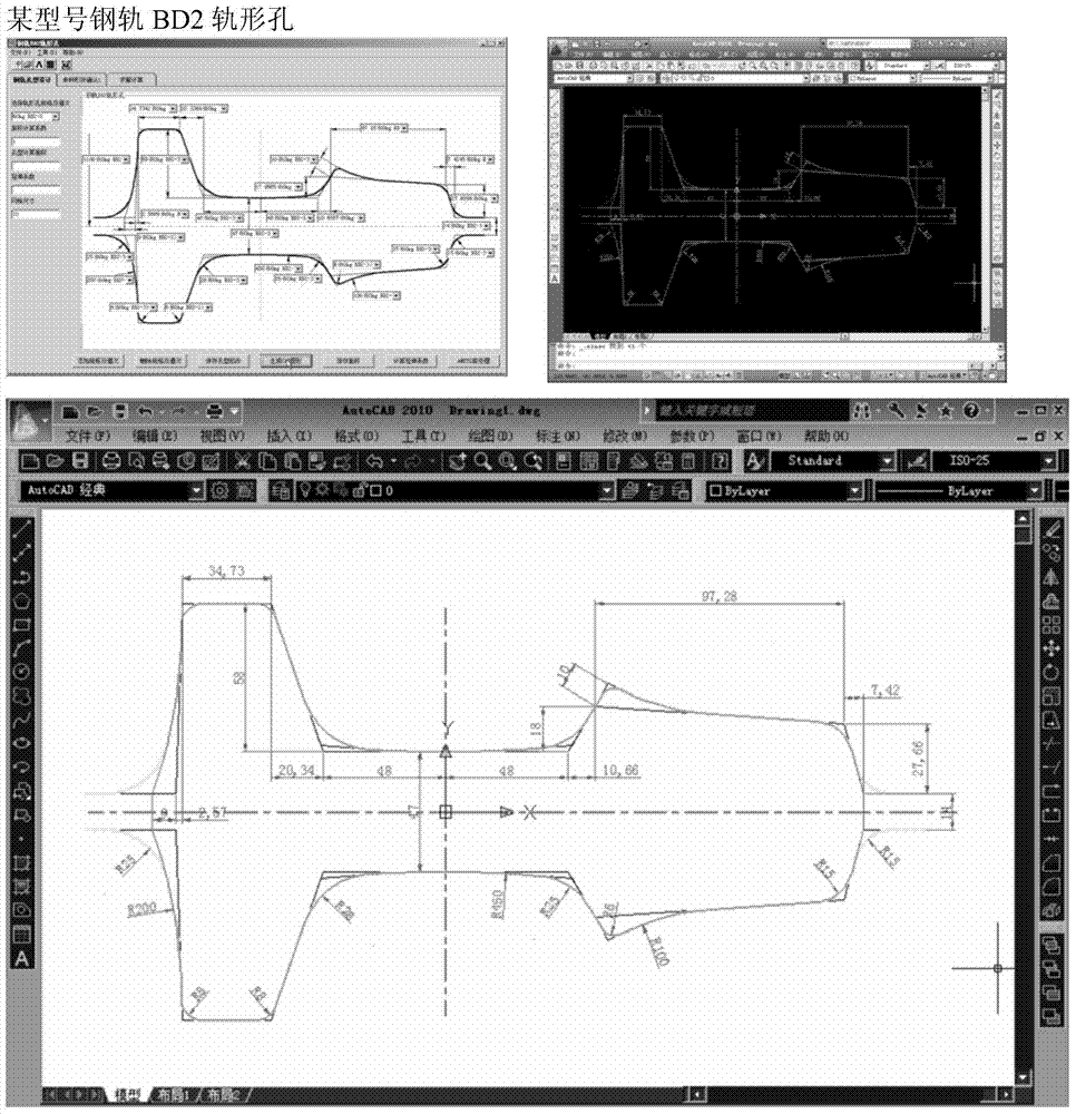
[0075] (1) First, according to the secondary development module of AutoCAD, calculate the position of each key point of the BD1 roll, and generate the CAD graphics of the BD1 roll.
[0076] (2) According to the position of each key point of the BD1 roll, combined with the format of the on-site CNC machiningmachine tool system, a machining code that can be recognized by machining is generated, and its realization code is:
PUM
Abstract
The invention discloses a simulation design method for rolling hole patterns of a steel rail, and belongs to the technical field of design and manufacturing of steel rail rolling equipment. The simulation design method for the rolling hole patterns of the steel rail, provided by the invention, is convenient to operate, high in automation degree and capable of improving the simulation analysis accuracy and avoiding errors. The method comprises the following steps: developing a set of simulation designsoftware comprising a CAD (Computer Aided Design) hole pattern design module, a CAE (Computer Aided Education) hole pattern optimization module and a CAM (Computer Aided Manufacturing) hole pattern processingcode generation module, and calling corresponding database information through the modules respectively; designing the rolling hole patterns of all rolling passes of the steel rail, dividing finite element grids for the rolling hole patterns with different specifications, establishing and correcting a related boundary condition model, and generating CAM codes of the rolling hole patterns of rollers corresponding to all the rolling passes. Due to the fact that the design and optimization of the rolling hole patterns of the steel rail and the generation of CAMprocessing codes are completed through the software respectively, the operation is simplified, the efficiency is improved, and the production cost is reduced.
Description
technical field [0001] The invention relates to a simulation design method, in particular to a simulation design method for rail rolling passes, and belongs to the technical field of design and manufacture of rail rolling equipment. Background technique [0002] The design of the current rail rolling pass is carried out in the following steps: [0003] Step 1: Manually design the pass pattern, that is, use CAD software to directly give the CAD drawing of the rail rolling pass pattern manually. The pass pattern is the disassembled mold, and the rectangular billet is rolled into rails through different pass patterns. The current design method is to manually draw a sketch of the pass after determining the pass system, and then mark the design dimensions on the sketch. Calculation of key design parameters such as rate. Labor-intensive and time-consuming. [0004] The second step: pass design optimization, commonly known as CAE simulation optimization. The accuracy and quali...
Claims
Application Information
Patent Timeline
Application Date:The date an application was filed.
Publication Date:The date a patent or application was officially published.
First Publication Date:The earliest publication date of a patent with the same application number.
Issue Date:Publication date of the patent grant document.
PCT Entry Date:The Entry date of PCT National Phase.
Estimated Expiry Date:The statutory expiry date of a patent right according to the Patent Law, and it is the longest term of protection that the patent right can achieve without the termination of the patent right due to other reasons(Term extension factor has been taken into account ).
Invalid Date:Actual expiry date is based on effective date or publication date of legal transaction data of invalid patent.

