Supercharge Your Innovation With Domain-Expert AI Agents!

Rolling Stock Systems

A technology for railway vehicles and vehicles, which is applied in the direction of railway vehicles, vehicle energy storage, vehicle components, etc. It can solve problems such as difficulty in connecting together and failure to connect power storage devices together, and achieve the effect of relaxing restrictions

Inactive Publication Date: 2016-12-14
MITSUBISHI ELECTRIC CORP
View PDF6 Cites 0 Cited by
  • Summary
  • Abstract
  • Description
  • Claims
  • Application Information

AI Technical Summary

Problems solved by technology

Therefore, in the railway vehicle system of Patent Document 1, it is considered that there is a problem in that the railway vehicle system is based on the premise of using a single type of power storage device, and it is impossible or difficult to connect power storage devices with different characteristics.

Method used


Image

  • Rolling Stock Systems
  • Rolling Stock Systems
  • Rolling Stock Systems

Examples


Embodiment approach 1

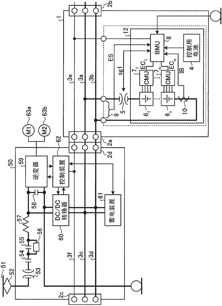
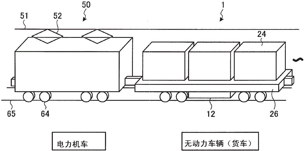
[0024] figure 1 It is a diagram showing a configuration example of the railway vehicle system according to Embodiment 1 of the present invention. As shown in the figure, the railway vehicle system according to Embodiment 1 is constituted by an electric locomotive 50 as a powered vehicle and an unpowered vehicle (for example, a freight vehicle) 1 equipped with an electric storage device 12 as a second electric storage device. The electric locomotive 50 is equipped with a power storage device 61 as a first power storage device, and includes an inverter 59, a DC / DC converter 60 that is a first DC / DC converter, a control device 62, a drive motor 63, and the like. Drive Control Department.

[0025] The structure of the electric locomotive 50 is as follows: the electric locomotive 50 receives DC power from a power supply source not shown in the figure, that is, a substation via a DC overhead line 51 and a pantograph 52, and further uses an inverter 59 to pass through the circuit br...

Embodiment approach 2

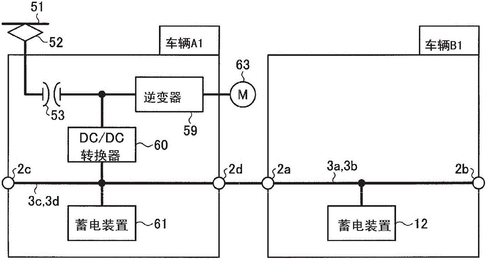
[0049] Figure 7 It is a figure which shows a structural example of the railway vehicle system concerning Embodiment 2. The difference between the railway vehicle system according to Embodiment 2 and Embodiment 1 lies in that: the arrangement position of the first DC / DC converter (DC / DC converter 60 ) in the electric locomotive 50 is different; A DC / DC converter (second DC / DC converter) for the first DC / DC converter. More specifically, in Embodiment 2, the power storage device 61 of the electric locomotive 50 is connected between the DC buses 3c and 3d via the DC / DC converter 60 . Furthermore, in Embodiment 2, power storage device 12 of unpowered vehicle 1 is connected between DC buses 3 a and 3 b via DC / DC converter 33 which is a second DC / DC converter. According to this structure, the voltage detector 32 which detects the voltage of the output terminal of the power storage device 12 side of the DC / DC converter 33 is provided. Also, with respect to other structures, with ...


PUM


Abstract

The electric locomotive (50) of the present invention is provided with: a first control line (3f) erected between the connectors (2c, 2d); a DC bus (3c, 3d); an electric storage device (61); and a DC / DC converter (60) for controlling charging and discharging of the electric storage device (61). The unpowered vehicle (1) is provided with: DC busbars (3a, 3b) connected to the DC busbars (3c, 3d) via a connector (2a); a second control line (3e); A power storage device (12) connected to the bus bars (3a, 3b); and a BMU (8) that manages the power storage device (12). The DC / DC converter (60) performs power storage control on the power storage device (61), and performs power storage control on the power storage device (12), and when the BMU (8) determines that the power storage device (12) is abnormal Next, the circuit breaker (5) is controlled to be turned off, thereby cutting off the electrical connection between the power storage device (12) and the DC bus (3a, 3b).

Description

technical field [0001] The present invention relates to a railway vehicle system including an electric storage device. Background technique [0002] As a railway vehicle system equipped with a power storage device, there is the following description: For example, in the railway vehicle drive system described in Patent Document 1, a power management unit is provided, which controls the power generated by the power generation unit and the power of the power storage unit as the power storage device. The amount of storage is controlled. The power storage device stores the power generated by the power generation unit and regenerative power. The power generation unit and the power storage unit are used as power sources to drive the drive motor by the power conversion unit to drive the train. [0003] prior art literature [0004] patent documents [0005] Patent Document 1: Japanese Patent Laid-Open No. 2005-27447 Contents of the invention [0006] The technical problem to be...

Claims


Application Information

Patent Timeline
Patent Type & Authority Patents(China)
IPC IPC(8): B60L11/18B61C3/02
CPCB61C3/02B60L3/0046B60L3/04B60L7/14B60L7/26B60L9/22B60L2210/10B60L2240/12B60L2240/545B60L2240/547B60L2240/549B60L2200/26B60L15/32B60L15/36B60L15/42B60L50/53B60L50/51B60L58/10B60L58/14B60L58/21B60L58/22B60L58/20B60L58/15B60L58/19B60L58/24Y02T10/70Y02T10/72Y02T30/00B60L1/00B60L7/16B60L2240/66B61C3/00B60L9/00
Inventor 畠中启太
Owner MITSUBISHI ELECTRIC CORP
Features
  • R&D
  • Intellectual Property
  • Life Sciences
  • Materials
  • Tech Scout
  • Unparalleled Data Quality
  • Higher Quality Content
  • 60% Fewer Hallucinations
Learn More