Sensor element with acoustic emission sensor

A sensing element and sensor technology, applied in the field of sensing elements, can solve problems such as expensive, unsuitable for industrial environment integration, complex equipment, etc.

Inactive Publication Date: 2014-12-17
SIEMENS AG
View PDF6 Cites 7 Cited by
  • Summary
  • Abstract
  • Description
  • Claims
  • Application Information

AI Technical Summary

Problems solved by technology

However, the equipment thus required is complex and expensiv

Method used


Image

  • Sensor element with acoustic emission sensor
  • Sensor element with acoustic emission sensor

Examples


Embodiment Construction

[0019] The examples described further below illustrate preferred embodiments of the invention.

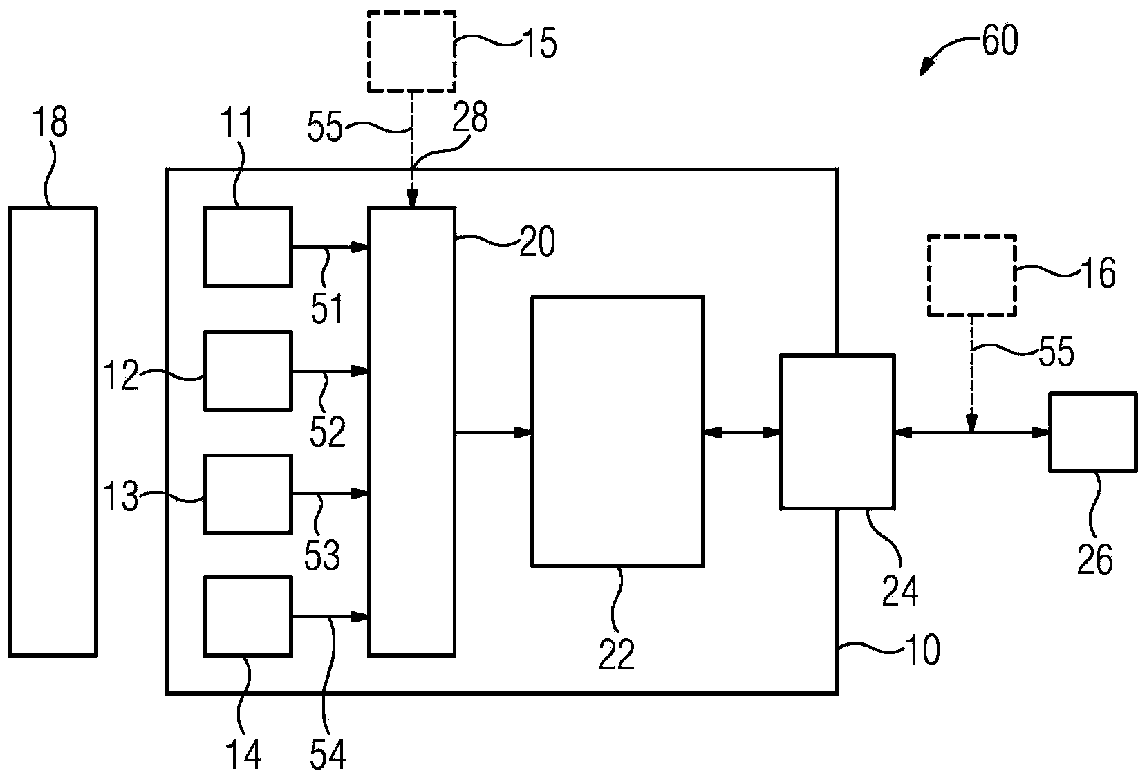
[0020] figure 1 The shown monitoring system 60 for monitoring a monitoring object 18 includes the superordinate monitoring device 26 and the sensor element 10 connected thereto. The sensor element 10 comprises a plurality of sensors 11, 12, 13, 14 for detecting physically different measured variables, a data detection circuit 20, an evaluation of the measured measured values ​​51, 52, 53, 54, 55 device 22 and an interface 24 connected to a superordinate monitoring device 26 .

[0021] Said first sensor 11 is an acoustic-emission sensor for generating an electrical signal related to the intensity and / or direction of the measured acoustic emissions. The second sensor 12 is a temperature sensor for generating an electrical signal related to the measured temperature level and / or the strength and / or direction of the temperature gradient. The third sensor 13 is an oscillation sensor f...


PUM


Abstract

The invention relates to a sensor element (10) comprising an acoustic emission sensor (11) for detecting acoustic emission (41) for the aim of simplifying measurement tasks. The sensor element comprise a second sensor (12) for a second measured variable (42, 45), with the second sensor (12) being different from the acoustic emission (41). Furthermore, the sensor element (10) comprising the acoustic emission sensor (11) for detecting the acoustic emission (41) is provided and comprises an interface (24, 28) for receiving an external sensor signal (15, 16).

Description

technical field [0001] The invention defines a sensor element with an acoustic emission sensor for detecting acoustic emissions in each case from two different aspects. Furthermore, the invention relates to a monitoring system, in particular a corrosion monitoring system, a bearing monitoring system or a machine monitoring system. Background technique [0002] Condition monitoring of industrial equipment is increasingly meaningful. In the following the term "acoustic-emission" is used. In the professional world, this foreign-language concept, which has become a technically precise expression, also includes structural noise, which does not exist in reversible material changes, but only in irreversible material changes. The evaluation of structure-borne noise in the ultrasonic region (acoustic emission) is considered as a tool for identifying material defects and material aging processes. In a range of applications, acoustic emission provides special signals that enable inf...

Claims


Application Information

Patent Timeline
IPC IPC(8): G01N29/14G01N29/50G01D5/14G01H1/00G01M15/05G01R33/02G01M13/04
CPCG01D5/145G01H1/00G01M13/028G01M13/045G01M15/05G01N29/14G01N29/50G01R33/07G01N2291/044G01R33/02
Inventor 汉斯-亨宁·克洛斯阿尔诺·哈施克迪尔克·沙伊布纳于尔根·席默尔罗纳德·威格尔
Owner SIEMENS AG
Why Eureka
Try Eureka