Heart rhythm recognition circuit and method with high reliability and low calculation load suitable for wearable devices

A wearable device and identification circuit technology, which is applied in the measurement of pulse rate/heart rate, application, diagnostic recording/measurement, etc., can solve the problems of not being able to meet the further needs of health, original signal interference, and high calculation load, and achieve low power consumption, Effects with low requirements and low signal-to-noise ratio

Active Publication Date: 2017-03-01
CHENGDU VCARE QINYUAN HEALTH TECH
View PDF3 Cites 0 Cited by
  • Summary
  • Abstract
  • Description
  • Claims
  • Application Information

AI Technical Summary

Problems solved by technology

[0002] With the progress of society and the improvement of living standards, people's demand for health is getting higher and higher. The traditional health management model aimed at seeing a doctor can no longer meet people's further needs for health. People hope to get a beautiful environment. , Physical and mental comfort, green and harmless, comprehensive and accurate, economical and convenient, and a new detection method that can prevent problems before they happen
[0003] In wearable health monitoring devices, it is generally necessary to calculate heart rhythm from electrocardiogram (ECG) signals, photoplethysmography (PPG) signals, and resistive volumetric signals. In new everyday wearable devices, because Due to human movement and environmental interference, the original signal is often mixed with a large number of interference signals, and the method often requires high calculation and high power consumption

Method used


Image

  • Heart rhythm recognition circuit and method with high reliability and low calculation load suitable for wearable devices
  • Heart rhythm recognition circuit and method with high reliability and low calculation load suitable for wearable devices
  • Heart rhythm recognition circuit and method with high reliability and low calculation load suitable for wearable devices

Examples


Embodiment Construction

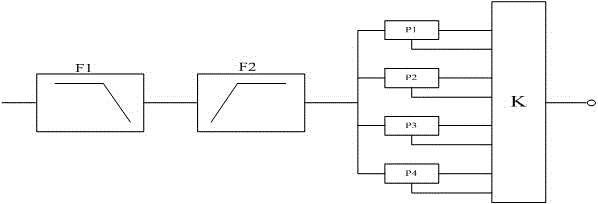
[0026] Describe technical scheme of the present invention in further detail below in conjunction with accompanying drawing: as figure 1 As shown, F1 is a low-pass filter, F2 is a high-pass filter, K is the control logic, P2 is the normally open software phase-locked loop, P2 covers the common heart rate range of the human body (60-90 beats per minute), P1, P3 , P4 is the backup software phase-locked loop, the normally open software phase-locked loop and the backup software phase-locked loop effectively lock the frequency range to cover the possible heart rate range of the whole human body (45-200 beats per minute). In addition to outputting the heart rate, each phase-locked loop also outputs valid locking signal strength and frequency overflow flags. Each phase-locked loop can also be independently enabled, and the control logic can turn off or turn on each phase-locked loop.

[0027] The P2 PLL cannot be shut down and is always running. In most cases, only the P2 PLL is runn...


PUM


Abstract

A highly reliable and low computational load heart rhythm recognition circuit and method applicable in a wearable device. The circuit comprises at least one software filter, one normally open software phase-locked loop, at least one backup software phase-locked loop, and at least one control logical unit K. Each backup software phase-locked loop is connected in parallel to the normally open software phase-locked loop. A signal output end of the software filter is connected respectively to the normally open software phase-locked loop and the backup software phase-locked loop. The normally open software phase-locked loop and each backup software phase-locked loop respectively comprise a heart rhythm signal output end and a frequency overflow flag output end. The heart rhythm signal output ends and the frequency overflow flag output ends respectively are connected to control logical unit K. The circuit has a lowered requirement on the signal-to-noise ratio of a signal, great robustness, and a broad recognition range. The method has an extremely low requirement on a processor, low power consumption, high reliability, and low computational load and is applicable in a wearable device.

Description

technical field [0001] The invention relates to a heart rhythm identification circuit and method suitable for wearable devices with high reliability and low calculation load. Background technique [0002] With the progress of society and the improvement of living standards, people's demand for health is getting higher and higher. The traditional health management model aimed at seeing a doctor can no longer meet people's further needs for health. People hope to get a beautiful environment. , Physical and mental comfort, green and harmless, comprehensive and accurate, economical and convenient, and a new detection method that can prevent problems before they happen. [0003] In wearable health monitoring devices, it is generally necessary to calculate heart rhythm from electrocardiogram (ECG) signals, photoplethysmography (PPG) signals, and resistive volumetric signals. In new everyday wearable devices, because Due to human movement and environmental interference, the origin...

Claims


Application Information

Patent Timeline
Patent Type & Authority Patents(China)
IPC IPC(8): A61B5/024A61B5/04
CPCA61B5/024
Inventor 崔予红
Owner CHENGDU VCARE QINYUAN HEALTH TECH
Why Eureka
Try Eureka