
Guide support for accurate puncture under CT

A precise and guide rail technology, applied in the field of brackets, can solve the problems of increased error, uncontrollable puncture needle offset, uncontrollable accuracy and safety, etc., and achieve the effect of reducing error

Inactive Publication Date: 2014-12-24
HUADONG HOSPITAL
View PDF6 Cites 10 Cited by
  • Summary
  • Abstract
  • Description
  • Claims
  • Application Information

AI Technical Summary

Problems solved by technology

[0004] 1. Completely bare-handed puncture: completely rely on experience, lack of definite reference objects, accuracy and safety cannot be controlled
[0005] 2. Protractor positioning: The error is 5-10 degrees, but two people are required to cooperate, and the observer needs to constantly adjust the horizontal state of the protractor. In addition, it is impossible to ensure that the puncture needle falls completely in the vertical plane where the CT scan is located
[0006] 3. Fixed guide rail: only suitable for single-point puncture, radioactive seed implantation requires simultaneous multi-point puncture, and it is difficult for the instrument to move accurately
[0007] 4. There is a plumb line and protractor on the puncture needle: it only displays the relative angle to the plumb line, and cannot control the offset of the puncture needle on the sagittal plane
[0008] 5. Laser guidance: Due to the flexibility of skin tissue during puncture, the skin puncture point often has a slight offset, but if the tail of the needle is still used as the aiming point of the laser, the error will continue to increase during the process of advancing, and there will be lateral impact on the tissue. damage

Method used


Image

  • Guide support for accurate puncture under CT

Examples


Embodiment Construction

[0022] The embodiments of the present invention are described in detail below. This embodiment is implemented on the premise of the technical solution of the present invention, and detailed implementation methods and specific operating procedures are provided, but the protection scope of the present invention is not limited to the following implementation example.

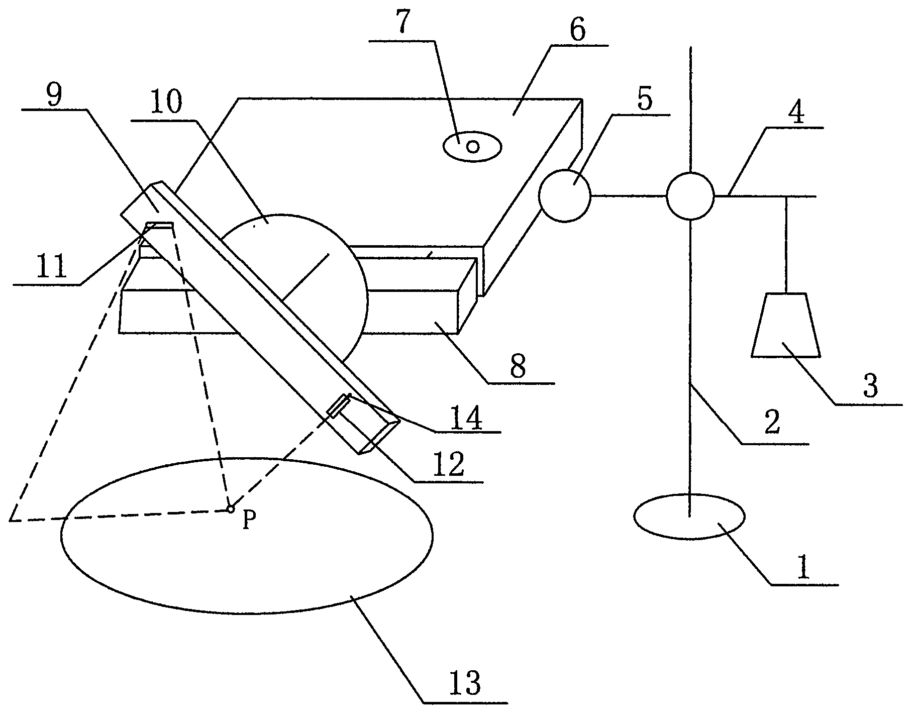
[0023] like figure 1 As shown, the present embodiment includes a chassis 1, a pole 2, a counterweight 3, a cross bar 4, a horizontal platform 6, a horizontal part 8, a rotating lever 9 and a protractor 10, and the pole 2 is fixed on the chassis 1, and the horizontal The rod 4 is supported on the vertical rod 2, one end of the cross bar 4 hangs a balance object 3, and the other end is connected to the horizontal platform 6, the balance object 3 can be any weight, the balance object 3 and the horizontal platform 6 are balanced, and the horizontal parts are 8 Connected with the horizontal platform 6, the protractor 1...


PUM


Abstract

The invention discloses a guide support for accurate puncture under CT. A vertical rod is fixed on a base plate, and a cross bar is supported on the vertical rod. A counterweight is hung at one end of the cross bar, the other end of the cross bar is connected with a horizontal platform, and the counterweight and the horizontal platform are balanced. A horizontal branch piece is connected with the horizontal platform, a protractor is placed between a rotating lever and the horizontal branch piece, and the protractor is fixed on the horizontal branch piece. The rotating lever is connected to the horizontal branch piece in a rotating mode, a correction laser lamp is arranged at one end of the rotating lever, and a puncture guide piece is arranged at the other end of the rotating lever. The puncture guide piece is arranged on the rotating lever in a sliding mode, the puncture guide piece is parallel to a pointer of the protractor, and a laser needle is arranged in the puncture guide piece. The guide support is provided with a level gauge, and after correction, the puncture needle can be kept in the vertical plane; a laser positioning system is arranged, the plane where the puncture needle is placed can be perpendicular to the horizon and be perpendicular to the long axis at the same time, and therefore the plane of the puncture needle is completely consistent with the CT scanning plane.

Description

technical field [0001] The invention relates to a bracket used under CT guidance, in particular to a guiding bracket for precise puncture under CT. Background technique [0002] In recent years, minimally invasive techniques have been rapidly developed and popularized, and a considerable part of the work is puncture of deep tissue targets under CT. Unlike puncture under B-ultrasound or DSA (Digital subtraction angiography), puncture under CT cannot be performed under real-time dynamic observation, and often requires multiple adjustments, which takes a long time and has large errors. The existing techniques are divided into the following categories: 1. Completely puncture with bare hands. Based on experience, after clarifying the puncture point on the body surface, estimate the approximate angle and depth, advance step by step, and adjust the position and angle through repeated CT scans. 2. Goniometer positioning: the assistant is on the side of the patient's foot, aiming at...

Claims


Application Information

Patent Timeline
Patent Type & Authority Applications(China)
IPC IPC(8): A61B6/03A61B19/00
Inventor 赵洪胡明华
Owner HUADONG HOSPITAL
Learn More