
Atomizing cleaning head for overhead transmission line

An overhead transmission line and atomization cleaning technology, which is applied to overhead line/cable equipment, chemical instruments and methods, cleaning methods and utensils, etc. Problems such as cleaning of lines and transmission lines, no design of closed and recycling loops, etc., to achieve the effect of easy replacement, low manufacturing cost, and avoid potential damage

Active Publication Date: 2014-12-24
STATE GRID INTELLIGENCE TECH CO LTD
View PDF8 Cites 13 Cited by
  • Summary
  • Abstract
  • Description
  • Claims
  • Application Information

AI Technical Summary

Problems solved by technology

There are following problems in cleaning: 1) the contact mechanical rotating brush is used as the cleaning device, and chemical reagents are not used, which can only clean the dust on the surface, but cannot clean the residual oil stains on the wires and the accumulation between the wire gaps. Dust and bird feces and other stains, 2) no airtight and recovery circuit is designed, flying dust, etc. are easy to contaminate the cleaned transmission lines again, thus forming secondary pollution of the cleaned lines
The equipment described in this patent is used for cleaning aluminum-clad steel wires before leaving the factory. This equipment cannot be used for cleaning overhead power transmission lines

Method used


Image

  • Atomizing cleaning head for overhead transmission line
  • Atomizing cleaning head for overhead transmission line
  • Atomizing cleaning head for overhead transmission line

Examples


Embodiment Construction

[0040] The present invention will be further described below in conjunction with the accompanying drawings and embodiments. This embodiment is carried out on the premise of the technical solution of the present invention, and the detailed implementation and specific operation process are given, but the protection scope of the present invention is not limited to the following embodiments.

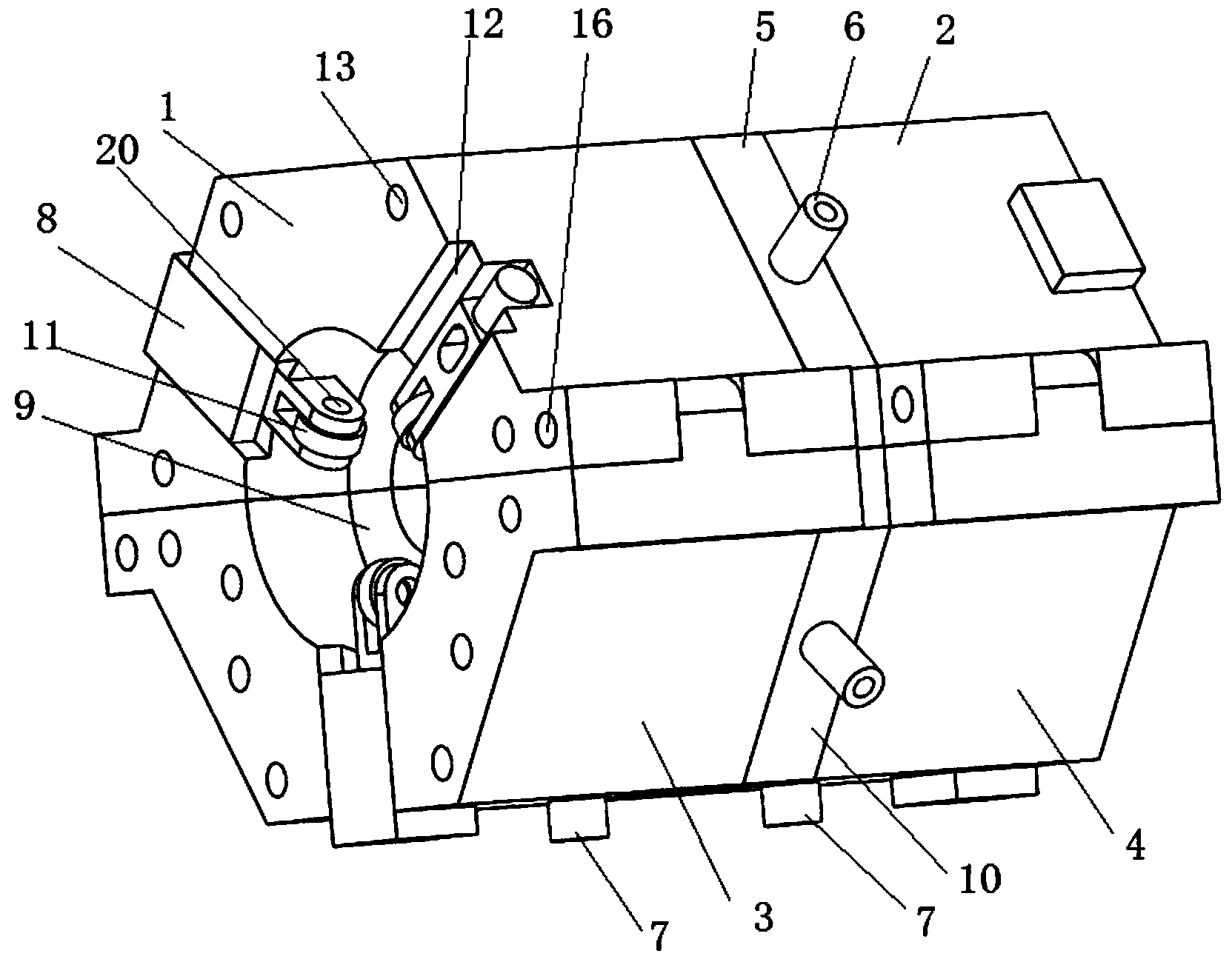
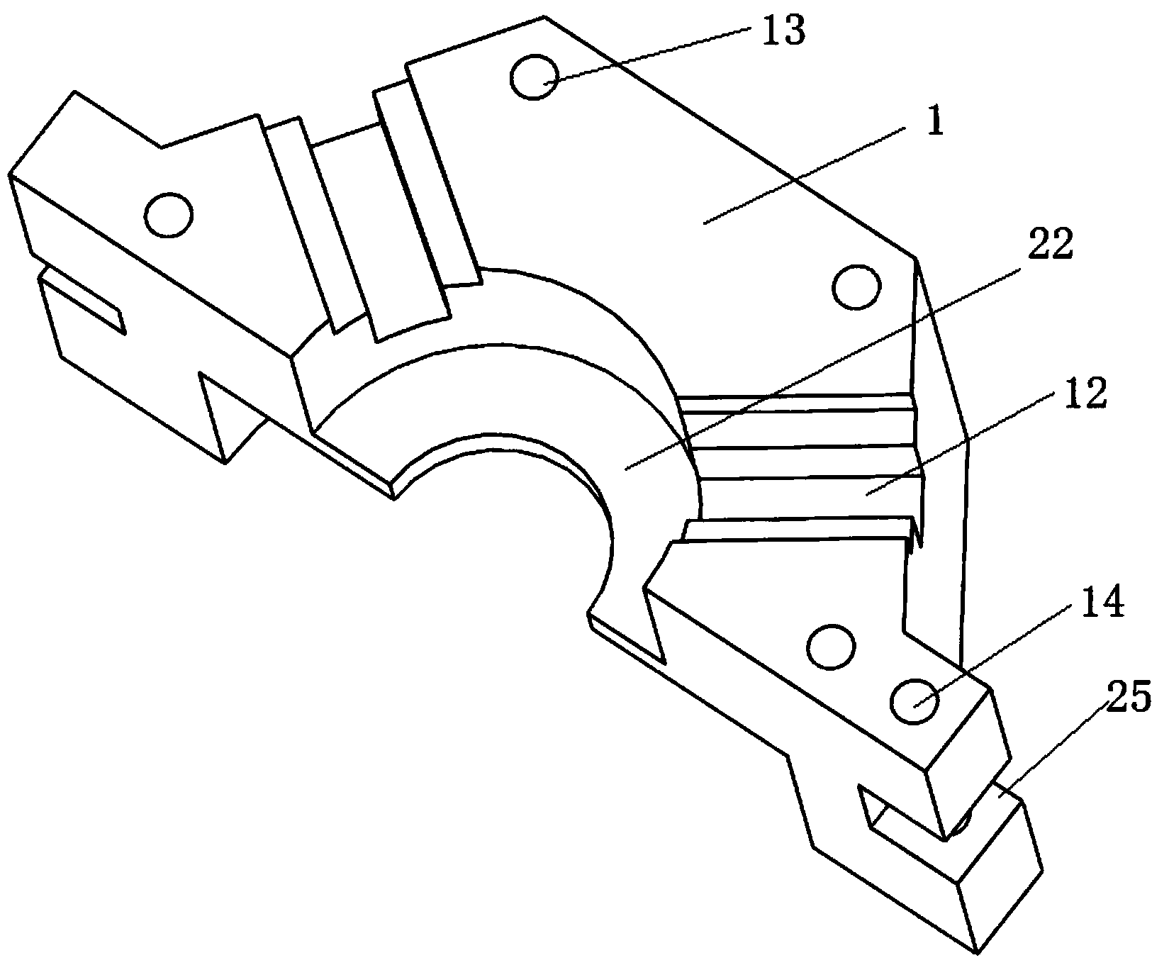
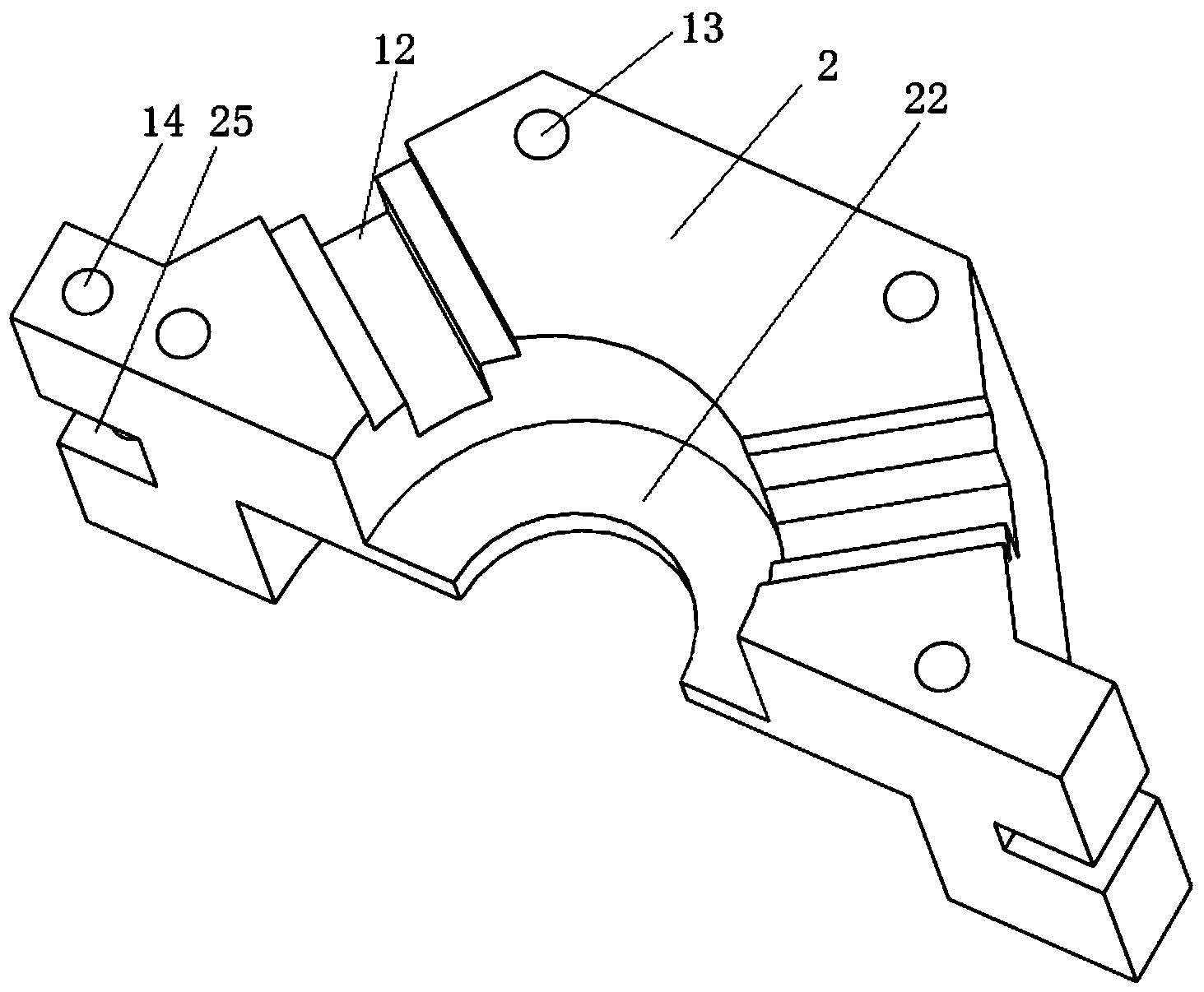
[0041] Such as figure 1 As shown, this embodiment includes: a cylindrical member composed of several modular structural connections, adopting a modular structural design form, the overall structure is simple, reliable, easy to replace, and low manufacturing cost. Two seals 9 arranged longitudinally in parallel are fixed in the middle of the inner cavity of the cylindrical member. There is a hole in the center of the seal 9 that only the power line for cleaning needs to pass through and the seal is sleeved on the power line. A seal is formed between the two seals 9. A cavity, the cavity is ...


PUM


Abstract

The invention discloses an atomizing cleaning head for an overhead transmission line. The atomizing cleaning head comprises a cylindrical member formed by connecting a plurality of module structures, wherein two sealing elements which are arranged longitudinally in parallel are fixed on the middle part of the inner cavity of the cylindrical member; a hole through which the transmission line needing to be cleaned passes and which is hermetically formed in the transmission line in a sleeving manner is formed in the center of each sealing element; a cavity is formed between the two sealing elements; a plurality of atomizing nozzles which are communicated to the outside of the cylindrical member are arranged along the circumferential direction of the cavity; a recycling nozzle which is communicated to the outside of the cylindrical member is arranged at the bottom of the cavity; compression walking mechanisms which can be compressed onto the transmission line and can move along the transmission line are arranged in the inner cavities at the two ends of the cylindrical member. Through adoption of a modular structural design form, the atomizing cleaning head is simple in overall structure, is reliable, is convenient to replace, and is low in manufacturing cost; during cleaning, the atomizing cleaning head is not in direct physical contact with the transmission line, so that potential damage to the surface of the transmission line is avoided, residual cleaning liquid can be recycled while atomizing cleaning is realized, and potential harm to the environment is avoided.

Description

technical field [0001] The invention relates to an atomizing cleaning head for an overhead power transmission line. Background technique [0002] At present, the overhead transmission lines laid in the early stage, especially the Southern Power Grid, generally adopt the form of bare wires to save construction costs. But there are also greater security risks. Kites and other sundries that are accidentally suspended on overhead transmission lines, and dust accumulated on insulators, clamps, and anti-vibration hammers can easily form mud flows and cause short circuits on the lines, thereby causing accidents such as tripping. In order to improve the transmission safety of bare overhead transmission lines, it is necessary to use artificial spraying of insulating varnish to improve its insulation performance. However, before manual spraying or machine spraying operations, it is necessary to use a cleaning solution to clean the exposed and leaked overhead transmission lines to re...

Claims


Application Information

Patent Timeline
Patent Type & Authority Applications(China)
IPC IPC(8): B08B3/02B08B3/08H02G1/02
CPCB08B3/02H02G1/02
Inventor 贾永刚郭锐慕世友任杰傅孟潮程志勇张峰曹雷仲亮贾娟高郎宏王滨海李建祥赵金龙
Owner STATE GRID INTELLIGENCE TECH CO LTD
Learn More