
Multifunctional flat-head milling cutter

A flat-end milling cutter, multi-functional technology, applied in milling cutters, milling machine equipment, manufacturing tools, etc., can solve the problems of inability to complete multiple processing jobs at one time, inability to save coolant, poor cooling effect, etc., and achieve shock absorption. Good effect, good cooling effect, vibration reduction effect

Inactive Publication Date: 2014-12-24
SHANGHAI HEHUA ELECTRONICS TECH
View PDF1 Cites 0 Cited by
  • Summary
  • Abstract
  • Description
  • Claims
  • Application Information

AI Technical Summary

Problems solved by technology

[0002] With the development of social production and the rapid development of the machinery industry, a large number of industrial tools are produced and used. The role of milling cutters in lathe operations cannot be ignored, and the application range of flat milling cutters is even wider. The application number is CN 03157155.7. A milling cutter, which is mainly provided with a spiral groove of appropriate depth from the edge of the milling cutter to the center of the section in a non-concentric manner on the cross-sectional surface of the milling cutter, and on the cross-sectional surface, the outer edge surface and the spiral groove of the milling cutter. The side is treated with plated drill or cast drill. When cooling with cooling liquid during grinding, drilling or milling, the cooling liquid can quickly flow into the spiral groove with the rotation of the milling cutter, fill it and discharge it quickly without stagnation. In the spiral groove, it can process hard materials and prolong the service life of the milling cutter, but the milling cutter cannot complete multiple processing tasks at one time, the efficiency is not high, and resources are wasted, and the cooling process cannot save coolant, and the cooling effect is not good. it is good

Method used


Image

  • Multifunctional flat-head milling cutter
  • Multifunctional flat-head milling cutter

Examples


Embodiment Construction

[0013] In order to make the technical means, creative features, goals and effects achieved by the present invention easy to understand, the present invention will be further described below in conjunction with specific illustrations.

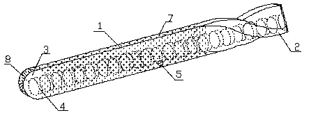
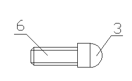
[0014] like figure 1 and figure 2 As shown, a kind of multifunctional flat end milling cutter of the present invention comprises a handle 1, the handle 1 is provided with a flat cutter head 2, and the end of the handle 1 away from the flat cutter head 2 is provided with a circle Arc-shaped cutter head 3, described knife handle 1, flat cutter head 2 and circular arc-shaped cutter head 3 interiors are all provided with spiral through-hole 4 along transverse center line, described knife handle 1 is provided with circular hole 5, described The round hole 5 is connected to the spiral through hole 4, and the combination of the flat cutter head and the arc-shaped cutter head can complete multiple processing tasks at one time, improve efficiency, save...


PUM


Abstract

The invention discloses a multifunctional flat-head milling cutter, and relates to the field of industrial machinery. The multifunctional flat-head milling cutter comprises a cutter handle, wherein the cutter handle is provided with a flat cutter head; one end of the cutter handle, which is far away from the flat cutter head, is provided with a circular arc cutter head; the cutter handle, the flat cutter head and the circular arc cutter head are internally provided with spiral through holes along the horizontal central lines; the cutter handle is provided with round holes connected with the spiral through holes. The multifunctional flat-head milling cutter has the characteristics that the flat cutter head is combined with the circular arc cutter head so as to complete multiple processing operations one time, so that the efficiency is improved, and resources are saved; a cooling fluid flows into the spiral through holes from the round holes so as to cool down the milling cutter; because the fluid flows spirally, the cooling fluid can be saved, and has a good cooling effect; the multifunctional flat-head milling cutter is reasonable in structure, is practical and convenient, and is suitable for popularization and using.

Description

technical field [0001] The invention relates to the field of industrial machinery, in particular to a multifunctional flat end milling cutter. Background technique [0002] With the development of social production and the rapid development of the machinery industry, a large number of industrial tools are produced and used. The role of milling cutters in lathe operations cannot be ignored, and the application range of flat milling cutters is even wider. The application number is CN 03157155.7. A milling cutter, which is mainly provided with a spiral groove of appropriate depth from the edge of the milling cutter to the center of the section in a non-concentric manner on the cross-sectional surface of the milling cutter, and on the cross-sectional surface, the outer edge surface and the spiral groove of the milling cutter. The side is treated with plated drill or cast drill. When cooling with cooling liquid during grinding, drilling or milling, the cooling liquid can quickly ...

Claims


Application Information

Patent Timeline
Patent Type & Authority Applications(China)
IPC IPC(8): B23C5/02B23C5/28B23C5/20
Inventor 郑小坚郭炎铭
Owner SHANGHAI HEHUA ELECTRONICS TECH
Learn More