Portable machining and observation integrated micro-miniature numerical control electric erosion machining machine tool
A portable machining and electro-erosion machining technology, applied in the field of CNC machine tools, can solve the problems of inability to use on-site video teaching demonstrations, and the large size of electro-erosion machining machine tools, and achieve the effects of easy expansion and upgrading, improved machining accuracy, and great flexibility.
- Summary
- Abstract
- Description
- Claims
- Application Information
AI Technical Summary
Problems solved by technology
Method used
Image
Examples
specific Embodiment approach 1
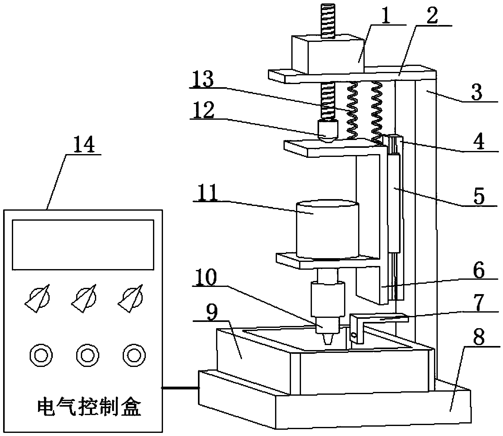
[0023] Specific implementation mode one: see figure 1 Describe this embodiment, the portable processing and observation integrated miniature numerical control electric erosion machining machine tool described in this embodiment, it includes a miniature machine tool body structure, a servo feed mechanism, a servo actuator, an elastic element 13 and an electrical control box 14;
[0024] The body structure of the miniature machine tool includes a portable lightweight beam 2, a column 3, a workbench 8, a working fluid tank 9, a guide rail 4 and a slider 5;
[0025] The servo feed mechanism includes a linear stepper motor 1 and a non-rigid connection ball head 12;
[0026] The servo actuator includes a rotating motor 11, an electrode chuck 10 and a rotating motor fixing frame 6;
[0027] One end of the column 3 is vertically fixed with a portable lightweight beam 2, and the other end is fixed on the workbench 8. The workbench 8 is provided with a working fluid tank 9, and the lin...
specific Embodiment approach 2
[0033] Specific implementation mode two: see figure 1 Describe this embodiment. The difference between this embodiment and the portable processing and observation integrated miniature numerical control electric erosion machine tool described in the first embodiment is that it also includes a video and audio device 7, and the video and audio device 7 is fixed on the guide rail 4 on the side wall where it is located, and is located below the guide rail 4,
[0034] The video and audio device 7 is used to collect the working state information of the electrode clamped by the electrode chuck 10 and the working fluid tank 9, and send the collected information to the mobile terminal.
[0035] In this embodiment, real-time video display and audio monitoring are performed on the discharge phenomenon through the video and audio device 7, and are sent to mobile terminals, such as computers, tablets, mobile phones, etc., to facilitate observation, monitoring and measurement.
specific Embodiment approach 3
[0036] Specific implementation mode three: see figure 2 Describe this embodiment. The difference between this embodiment and the portable processing and observation integrated miniature CNC electro-erosion machining machine described in the first or second specific embodiment is that the electrical control box 14 includes a housing, a servo detection module 14- 1. Servo control module 14-2, servo drive module 14-3 and power supply module 14-4, the servo detection module 14-1, servo control module 14-2, servo drive module 14-3 and power supply module 14- 4. Set in the shell, the power module 14-4 is used to provide working power for the electrode chuck 10, the servo detection module 14-1, the servo control module 14-2 and the servo drive module 14-3,
[0037] The servo detection module 14-1 is used to detect the inter-pole voltage, and sends the obtained inter-pole voltage data to the servo control module 14-2, and the servo control module 14-2 is used to generate a linear ste...
PUM
 Abstract
Description
Claims
Application Information
 - R&D
- Intellectual Property
- Life Sciences
- Materials
- Tech Scout
- Unparalleled Data Quality
- Higher Quality Content
- 60% Fewer Hallucinations
Browse by: Latest US Patents, China's latest patents, Technical Efficacy Thesaurus, Application Domain, Technology Topic, Popular Technical Reports.
© 2025 PatSnap. All rights reserved.Legal|Privacy policy|Modern Slavery Act Transparency Statement|Sitemap|About US| Contact US: help@patsnap.com


