Bottle blowing structure and method

A preform and main blowing valve technology, applied in other household appliances, household appliances, applications, etc., can solve the problems of increasing the energy consumption of the compressed air of the container blowing machine, the processing cost of the container blowing machine, energy consumption, and the inability to recycle, etc. Achieve the effect of reducing energy consumption, reducing consumption and reducing supply

Inactive Publication Date: 2014-12-24
GUANGZHOU TECH LONG PACKAGING MACHINERY CO LTD
View PDF6 Cites 7 Cited by
  • Summary
  • Abstract
  • Description
  • Claims
  • Application Information

AI Technical Summary

Problems solved by technology

However, when the container blowing is completed, the gas discharged from the exhaust valve contains more energy, which cannot be recycled, resulting in a large amount of energy consum...

Method used


Image

  • Bottle blowing structure and method
  • Bottle blowing structure and method

Examples


Embodiment Construction

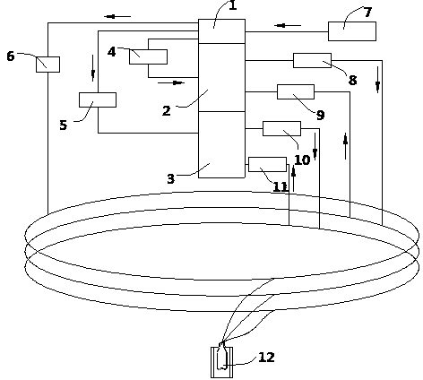
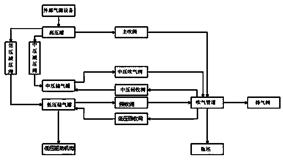
[0016] A bottle blowing structure such as figure 1 and figure 2 As shown, it includes a high-pressure tank 1 connected with an external air source device 7 pipelines, and the high-pressure tank 1 is respectively connected with a low-pressure pressure relief valve 5 and a main blow valve 6. The gas pipeline is connected with an exhaust valve through a pipeline on the blowing pipeline, and the low-pressure decompression valve 5 is communicated with the low-pressure gas storage tank 3 through the pipeline, and the low-pressure gas storage tank 3 is communicated with the pre-blowing valve 10 through the pipeline, and the pre-blowing The valve 10 communicates with the blowing pipeline through pipelines, and the low-pressure gas storage tank 3 also communicates with the low-pressure recovery valve 11 through pipelines, and the low-pressure recovery valve 11 communicates with the blowing pipeline through pipelines; After the pressure valve 5 is decompressed, it enters the low-press...


PUM


Abstract

The invention discloses a bottle blowing structure and method. By adopting the bottle blowing structure, gases in a container during the periods of primary bottle blowing and secondary bottle blowing are recycled, and the recycled low-pressure gases are applied to the next bottle blowing process, so that supply of low-pressure gases from an external gas source can be reduced, consumption of a high-pressure gas is further reduced, the utilization rate of energy sources is increased, energy consumption of compressed air supplied to a container blower by external gas source equipment and the machining cost of the container blower are reduced, and energy conservation and environment protection are achieved.

Description

technical field [0001] The invention relates to a container blowing machine, in particular to a bottle blowing structure and a bottle blowing method in the container blowing machine. Background technique [0002] The container blowing machine is widely used in the field of filling. At present, the bottle blowing structure in the container blowing machine includes a high-pressure tank connected with external air source equipment. The pressure valve communicates with the low-pressure gas storage tank through the pipeline, the main blow valve communicates with the blowing pipeline for bottle blowing, and the blowing pipeline communicates with the exhaust valve through the pipeline, and the low-pressure gas storage tank communicates with the pre-heating pipeline through the pipeline. The blowing valve is connected, and the pre-blowing valve is connected with the blowing pipe through a pipeline. When it is necessary to blow the preform, all the valves are closed first, then the ...

Claims


Application Information

Patent Timeline
IPC IPC(8): B29C49/28B29C49/58B29L22/00
CPCB29C49/28B29C49/58
Inventor 邹大群吴志刚宋奎伟郭利民刘青山
Owner GUANGZHOU TECH LONG PACKAGING MACHINERY CO LTD
Why Eureka
Try Eureka