
Method for operating a workstation of an open end rotary spinning machine and corresponding workstation

A rotor spinning machine, free-end technology, applied in open-end spinning machines, spinning machines, spinning machines with continuous winding, etc., can solve problems such as uncertain operating conditions, and achieve low-cost effects

Inactive Publication Date: 2014-12-24
SAURER GERMANY GMBH & CO KG
View PDF5 Cites 3 Cited by
  • Summary
  • Abstract
  • Description
  • Claims
  • Application Information

AI Technical Summary

Problems solved by technology

[0015] In fact, as mentioned above, when the winding speed of the cross-wound bobbin driven by the bobbin drive roller is slightly higher than the yarn delivery speed generated by the yarn take-off mechanism during the spinning operation, the remaining storage length is then slowly withdrawn from the storage mechanism again and wound onto cross-wound bobbins, but during this time a relatively indeterminate operating state occurs at the relevant station

Method used


Image

  • Method for operating a workstation of an open end rotary spinning machine and corresponding workstation
  • Method for operating a workstation of an open end rotary spinning machine and corresponding workstation

Examples


Embodiment Construction

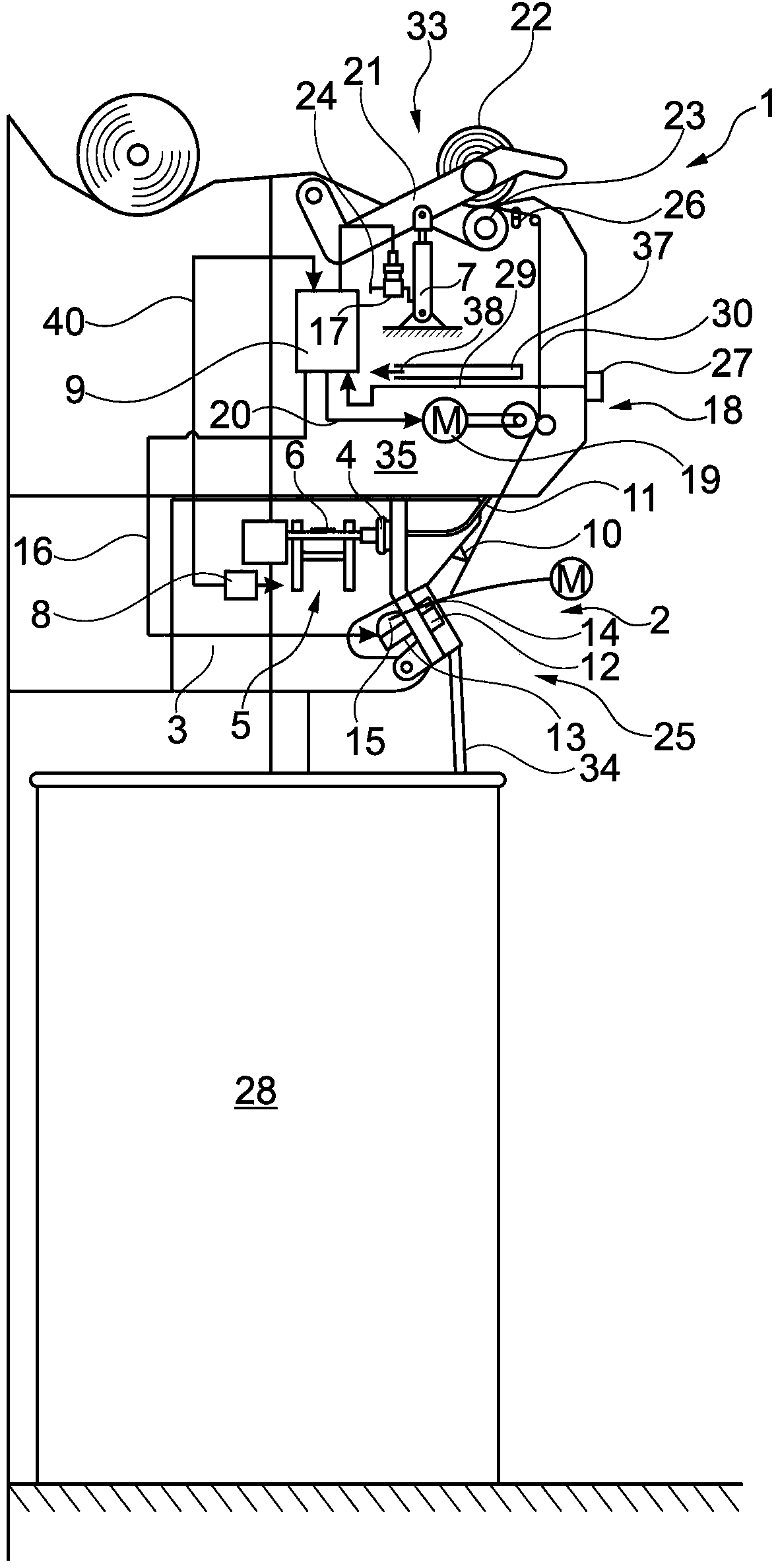
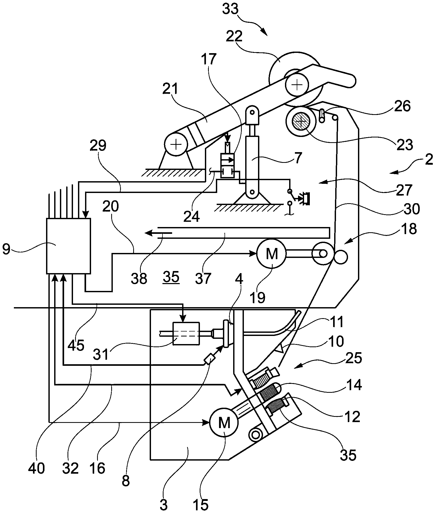
[0035] figure 1 Half of station 2 of semi-automatic open-end rotor spinning machine 1 is shown. As is known, this type of textile machine usually has a large number of stations 2 equipped with an open-end spinning device 3 and a winding device 33, respectively.

[0036] In the open-end spinning device 3, the fiber ribbon 34 supplied in the spinning bobbin 28 is spun to form the yarn 30, and the yarn 30 is wound on the winding device 33 to form a cross-wound bobbin 22. As known per se, the winding device 33 respectively has a creel 21 for holding the bobbin of the cross-wound bobbin 22 in a rotatable manner, a bobbin driving roller 23, a yarn traverse mechanism 26, and a yarn traverse mechanism 26 for winding the cross-wound bobbin 22. The bobbin 22 is lifted away from the mechanism 7 of the bobbin driving roller 23. The mechanism 7 is, for example, configured as a push rod transmission, which is connected to an overpressure source (not shown) via a pneumatic line 24, in which a ...


PUM


Abstract

The invention relates to a method for operating a workstation of an open end rotary spinning machine and a corresponding workstation. The workstation is provided with the open end rotary spinning machine having a spinning machine capable of high speed rotation in a rotary cup housing; a fiber ribbon opening mechanism having an opening roller and a fiber ribbon supply drum drivn by a separate motor; a yarn removing mechanism driven by the separate motor to transport finished yarns; a yarn storage mechanism for halfway temporary storage of yarns with a certain length; and a winding device for generating a cross winding bobbin rotatably held in a creel. According to the invention, in the splicing process after the interruption of the winding at the workstation (2), the yarn transport speed of the finished yarns (30) from the yarn removing mechanism (18) is temporarily reduced to such a level lower than a predetermined yarn transport speed at the corresponding workstate in the spinning process.

Description

Technical field [0001] The invention relates to a method for operating a station of a free-end rotor spinning machine and an associated station. Background technique [0002] Open-end rotor spinning machines are widely used in the textile industry. These textile machines, which are described in detail in a large number of patent applications, usually have a large number of similar stations where the fiber ribbons supplied in the preferred spinning bobbin are spun to form yarns and then are wound to form cross-wounds. Around the bobbin. For this purpose, each station has a spinning device and a winding device, respectively. The working parts of the spinning device and the working parts of the winding device are usually driven by the drive device along the length of the machine. In other words, in known open-end spinning machines, tangential belts for driving the spinning rotor and fiber ribbon opening rollers and for driving the fiber ribbons along the length of the machine are ...

Claims


Application Information

Patent Timeline
Patent Type & Authority Applications(China)
IPC IPC(8): D01H4/08
CPCD01H4/44
Inventor 克里斯托夫·哈泽
Owner SAURER GERMANY GMBH & CO KG
Learn More