
High-frequency muffler used on automobile intercooler intake pipe

A technology of air intake pipe and muffler, which is applied in the direction of air intake muffler, etc., can solve the problems that the anechoic frequency band cannot cover the frequency range well, the control effect of broadband peak noise is poor, and the anechoic performance does not meet the requirements, etc., and meets the requirements The effect of small restriction, excellent noise reduction performance and small structural size

Inactive Publication Date: 2014-12-24
CHONGQING CHANGAN AUTOMOBILE CO LTD
View PDF6 Cites 15 Cited by
  • Summary
  • Abstract
  • Description
  • Claims
  • Application Information

AI Technical Summary

Problems solved by technology

[0003] At present, there are two main ways to solve high-frequency noise: (1) Add multiple (usually four) quarters to the intake pipe of the intercooler Wavelength tube, a quarter-wavelength tube is a tube with one end closed and one end open. It forms a side branch muffler together with the intercooler intake pipe. The quarter-wavelength tube has strong frequency selectivity, and only at the resonance frequency It can effectively eliminate noise in a narrow frequency range centered on the center, and has almost no noise elimination effect on other frequencies. Its unique noise reduction characteristics make it effective in controlling narrow-band peak noise, but for broadband peak noise The control effect is extremely poor; if more quarter-wavelength tubes are connected in parallel on the intake pipe of the intercooler, the anechoic frequency band (the anechoic bandwidth) can be appropriately increased. The number and layout of the wavelength tubes will be limited, so that the sound attenuation performance does not meet the requirements and is not beautiful
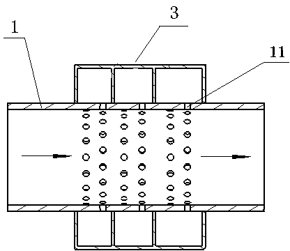
(2) Three resonant cavities (or more than three) are arranged side by side on the intake pipe of the intercooler to form a high-frequency noise reduction structure 3 (see Figure 1), each resonance cavity passes through a group of radial small round holes 11 on the intake pipe 1 of the intercooler and the intercooler The intake pipe 1 is connected, and the noise reduction effect of the high-frequency noise reduction structure 3 is obviously better than that of the quarter-wavelength tube, and there is no passing frequency. The diameter, number and volume of the resonant cavity together determine the bandwidth of a single anechoic peak. The more the number of resonant cavities, the more the number of anechoic peaks, which can widen the anechoic bandwidth to a certain extent; if the original resonance is maintained The number of cavities remains unchanged, and in the case of increasing the axial length (that is, the length of the cavity), optimizing the number of small round through holes and the diameter of the holes can also widen the noise reduction bandwidth to a certain extent; but this high-frequency noise reduction structure It will also be limited by the layout of the engine room, and its radial size and axial length can only be within a certain size range, which will affect the number of cavities of the resonant cavity and the number of small round through holes, so that the anechoic frequency band cannot well cover the required Frequency range, can not achieve a good noise reduction effect

Method used


Image

  • High-frequency muffler used on automobile intercooler intake pipe
  • High-frequency muffler used on automobile intercooler intake pipe
  • High-frequency muffler used on automobile intercooler intake pipe

Examples


Embodiment 1

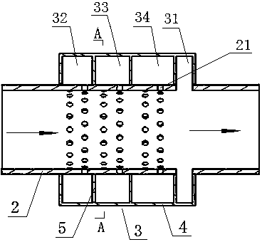
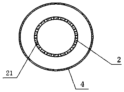
[0019] Example 1: like figure 2 , image 3 , Figure 4 The shown high-frequency muffler used on the intake pipe of the intercooler of an automobile includes a high-frequency noise reduction structure 3 and a main pipe 2 connected to the intake pipe 1 of the intercooler. The intake pipe 1 of the intercooler is divided into two sections, A section of the intake pipe close to the turbocharger is threaded to one end of the main pipe 2, and a section of the intake pipe near the intercooler is threaded to the other end of the main pipe 2; Closed shell 4, the outside of the closed shell 4 is provided with a high-frequency muffler fixing bracket 6, the closed shell 4 is provided with three circular partitions 5 along the radial direction, so that the closed shell 4 along the main pipe 2 The airflow direction of the first resonant cavity 32, the second resonant cavity 33, the third resonant cavity 34 and the expansion cavity 31 are sequentially formed, and the cavity lengths of th...

Embodiment 2

[0021] Example 2: Its main structure and principle are the same as that of Embodiment 1, except that only two partitions 5 are arranged in the closed casing 4, so that the high-frequency noise reduction structure is composed of two resonant cavities and one expansion cavity.

Embodiment 3

[0022] Example 3: Its main structure and principle are the same as that of Embodiment 1, except that four partitions 5 are arranged inside the closed casing 4, so that the high-frequency noise reduction structure is composed of four resonant cavities and one expansion cavity.


PUM


Abstract

The invention discloses a high-frequency muffler used on an automobile intercooler intake pipe. The high-frequency muffler comprises a high-frequency muffling structure and a main pipeline connected on the intercooler intake pipe; a closed shell is positioned and connected on the periphery of the main pipeline, at least two partitions are arranged in the closed shell radially to enable at least two resonant cavities and an expansion cavity to be formed in the closed shell, each resonant cavity is communicated with the main pipeline through a group of small round through holes formed in the circumference of the main pipeline, the expansion cavity is directly communicated with the main pipeline, and the resonant cavities and the expansion cavities jointly form the high-frequency muffling structure. In a limited engine room space, the high-frequency muffler is wider in muffling frequency band, excellent in muffling performance and capable of more effectively lowering high-frequency noise such as squeal and surge generated in the working process of a turbocharger.

Description

technical field [0001] The invention belongs to the technical field of automobile noise control, and in particular relates to a high-frequency muffler used on an air intake pipe of an automobile intercooler to reduce high-frequency noise such as whistling and surge generated during the working process of a turbocharger. Background technique [0002] With the application of turbocharging technology in automobile engines, while improving the dynamic performance of automobiles, the high-frequency noises such as whistling and surge generated by turbochargers are becoming more and more prominent, and gradually become the main source of noise in the car. main source of contribution. The frequency of this noise is mainly concentrated in the range of 1200Hz to 2500Hz, and some even reach 3000Hz. The frequency is high and the coverage is extremely wide. How to reduce the high-frequency noise such as howling and surge generated during the working process of the turbocharger and impr...

Claims


Application Information

Patent Timeline
IPC IPC(8): F02M35/12
Inventor 张冬莲魏鹏辉匡小红张海燕黎杰赵立峰杨亮张硕
Owner CHONGQING CHANGAN AUTOMOBILE CO LTD
Learn More