Deceleration buffer magnetic shield rotating shaft

A technology of rotating shaft and magnetic isolation, applied in the direction of shaft, shaft and bearing, spring/shock absorber, etc., can solve the problems of poor heat dissipation effect of motor rotor, large eddy current loss and shaft current, high performance requirements of rotating shaft, and achieve lower temperature. , weaken the magnetic flux, improve the effect of internal ventilation

Inactive Publication Date: 2014-12-24
NINGBO JIECHENG AXLE TRADE
View PDF4 Cites 4 Cited by
  • Summary
  • Abstract
  • Description
  • Claims
  • Application Information

AI Technical Summary

Problems solved by technology

[0002] The existing motor shaft is generally composed of the shaft and the rotor core fixed on it. Because the entire rotor is a solid core structure, the mass of the rotor is large. During the rotation of the rotor, the axial stress changes greatly. At the same time, there are motor rotor The cooling effect is not good
At present, there are also motor shafts composed of shaft and spoke iron plates on the market, thereby reducing the weight of the rotor, but the stress on the cross-section of the motor shaft with this structure is large, which is easy to cause the shaft to break. At the same time, this type of motor has poor ventilation performance. , so it cannot be well applied
Moreover, the magnetic field of the rotor core yoke will enter the motor shaft during the operation of the motor, which will cause large eddy current loss and shaft current inside the motor shaft, which will not only increase the loss of the motor, but also the shaft current will damage the bearing and cause the motor to appear. Quality problems, greatly reducing the life of the motor
[0003] At the same time, because the rotating shaft is under great stress during the working process, the rotating shaft controls one end of the rotating shaft, and then controls the other end of the rotating shaft to control the work of the machine. Therefore, the performance requirements of the rotating shaft are getting higher and higher, and the manufacturing cost of the rotating shaft is also getting higher and higher. In order to reduce the stress of the rotating shaft during the working process and improve the service life of the rotating shaft, the existing rotating shaft structure must be improved. , to reduce the workload of the shaft

Method used


Image

  • Deceleration buffer magnetic shield rotating shaft
  • Deceleration buffer magnetic shield rotating shaft

Examples


Embodiment Construction

[0014] The following will clearly and completely describe the technical solutions in the embodiments of the present invention with reference to the accompanying drawings in the embodiments of the present invention. Obviously, the described embodiments are only some, not all, embodiments of the present invention. Based on the embodiments of the present invention, all other embodiments obtained by persons of ordinary skill in the art without making creative efforts belong to the protection scope of the present invention.

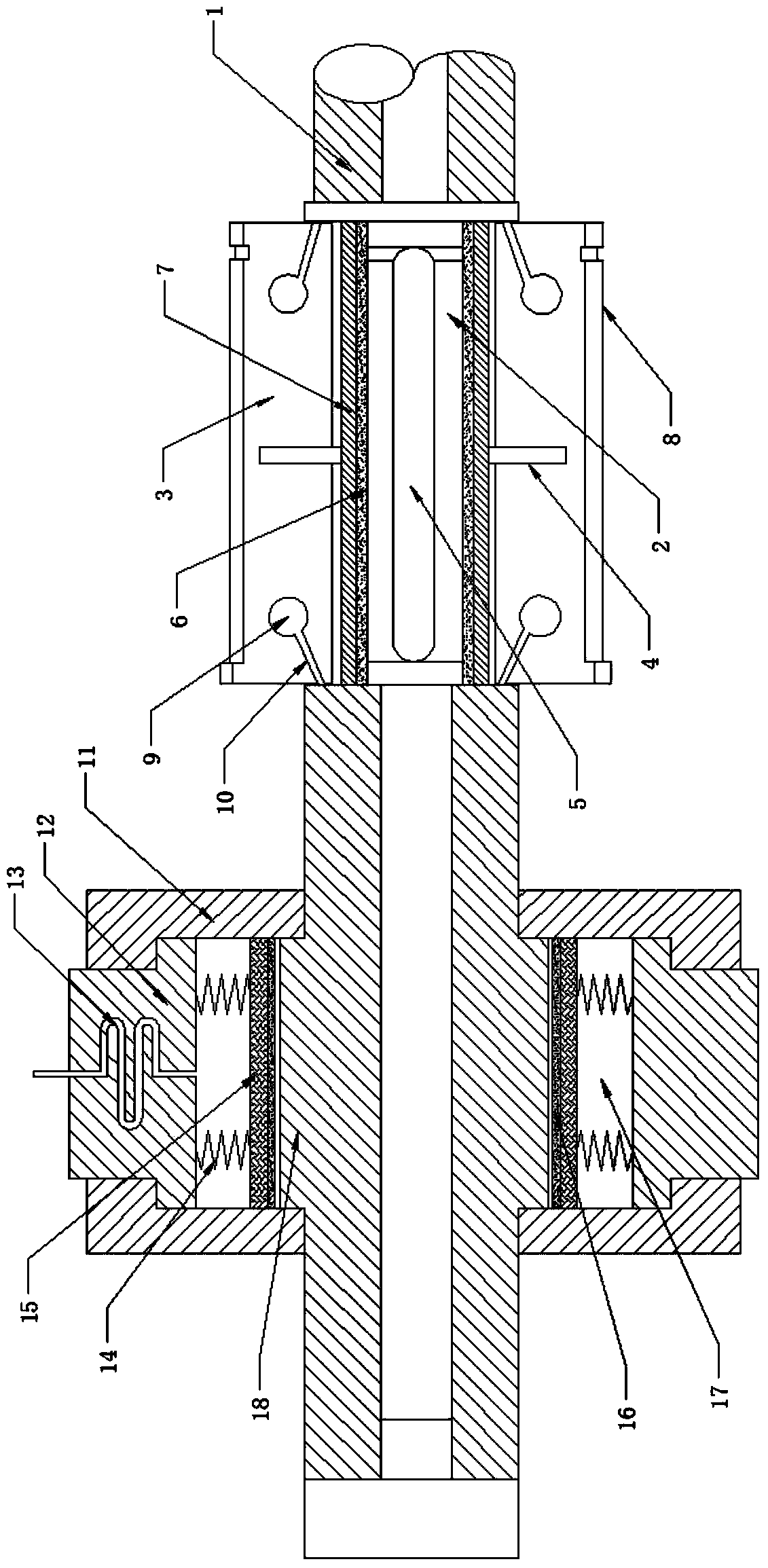
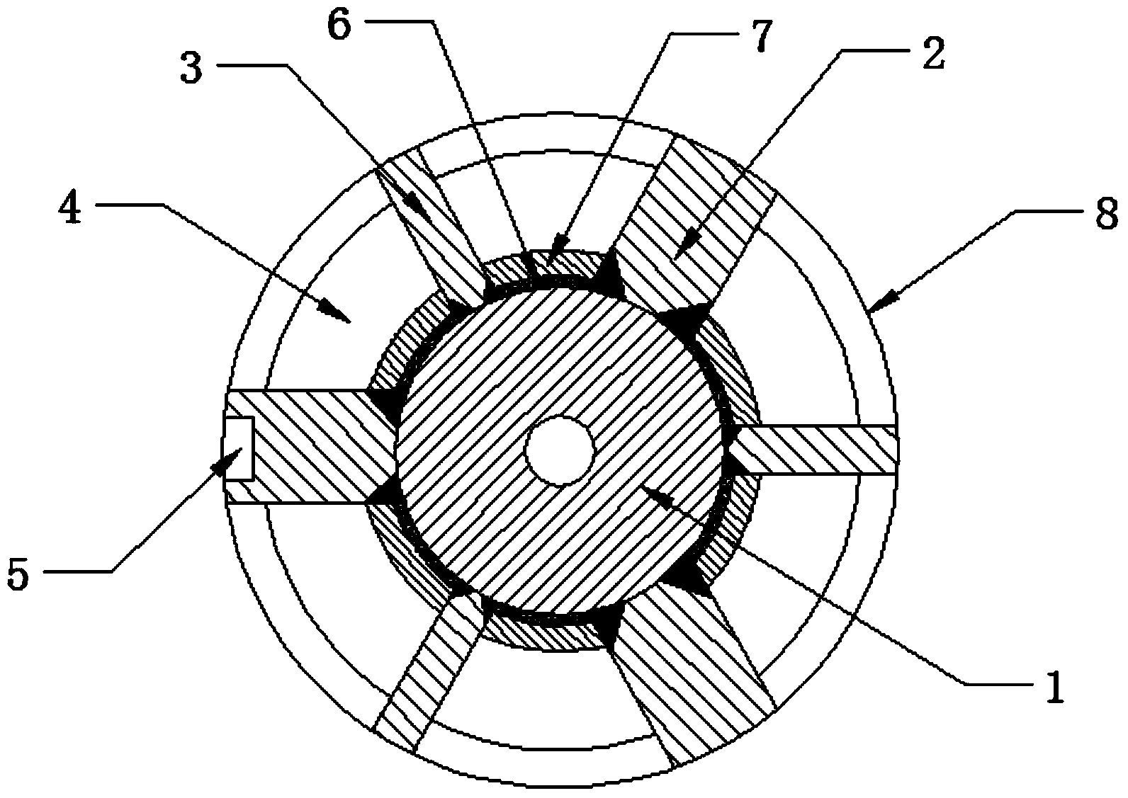
[0015] see Figure 1~2 , in an embodiment of the present invention, a deceleration and buffering magnetically isolated rotating shaft includes a rotating shaft 1 fixed in a rotor 8, three narrow-spoke iron plates 3, three wide-radius iron plates 2, a housing 11 and a buffer seat 12, The shaft 1 with hollow structure not only reduces its own weight, but also increases the ventilation problem inside the motor and reduces the temperature inside the motor; The un...


PUM


Abstract

The invention relates to a deceleration buffer magnetic shield rotating shaft which comprises a rotating shaft body arranged at the axis position of a rotor, narrow iron plates, wide iron plates, a casing and a buffer seat, wherein the narrow iron plates and the wide iron plates are uniformly distributed on the surface of the rotating shaft body in the axial direction of the rotating shaft body at equal intervals; a magnetic shield bushing and a fixing sleeve are arranged between every two adjacent iron plates; a wind flowing plate is arranged on the outer side of each fixing sleeve; a key groove is formed in the tail end of each wide iron plate; a through hole and a through groove are respectively formed in the side face of each iron plate; a bump is arranged on the rotating shaft body; the casing is arranged on the outer side of the bump; the buffer seat is arranged at an inlet of the casing; symmetrical springs are arranged between an elastic sleeve between the buffer seat and the bump and the buffer seat; a friction piece is arranged on the elastic sleeve; a buffer tube is arranged in the buffer seat. A motor rotating shaft disclosed by the invention has the advantages of reduced integral weight, low energy consumption, good heat radiating performance and low work load; the rotating shaft is not easy to damage, so the maintenance cost is low and the service life is long.

Description

technical field [0001] The invention relates to a motor rotating shaft, in particular to a decelerating and buffering magnetically isolated rotating shaft. Background technique [0002] The existing motor shaft is generally composed of the shaft and the rotor core fixed on it. Because the entire rotor is a solid core structure, the mass of the rotor is large. During the rotation of the rotor, the axial stress changes greatly. At the same time, there are motor rotor The cooling effect is not good. At present, there are also motor shafts composed of shaft and spoke iron plates on the market, thereby reducing the weight of the rotor, but the stress on the cross-section of the motor shaft with this structure is large, which is easy to cause the shaft to break. At the same time, this type of motor has poor ventilation performance. , so it cannot be well applied. Moreover, the magnetic field of the rotor core yoke will enter the motor shaft during the operation of the motor, whi...

Claims


Application Information

Patent Timeline
IPC IPC(8): F16C3/02F16F15/121F16D49/12H02K7/102H02K9/02
Inventor 冯建杰董国柱毛财德
Owner NINGBO JIECHENG AXLE TRADE
Why Eureka
Try Eureka