
Clutch stroke monitoring system

A clutch travel and monitoring system technology, applied in the field of clutches, can solve the problems of not being able to understand the number and state of clutch clutches, not being able to effectively judge the mechanical failure of the sensor, and being unable to effectively judge the mechanical failure of the sensor, so as to achieve automatic fault diagnosis and reduce labor intensity , Realize the effect of real-time monitoring

Active Publication Date: 2016-08-17
RUILI GROUP RUIAN AUTO PARTS CO LTD
View PDF8 Cites 0 Cited by
  • Summary
  • Abstract
  • Description
  • Claims
  • Application Information

AI Technical Summary

Problems solved by technology

However, the above-mentioned clutch operating system is not equipped with a monitoring system for the clutch stroke, and the resulting technical defects are: first, the customer can only rely on frequent visits to the chassis of the vehicle to check the extension length of the marking ruler to observe and judge Whether the friction plate of the clutch is excessively worn and needs to be replaced immediately, which undoubtedly increases the labor intensity and is extremely inconvenient; secondly, the customer cannot effectively judge the mechanical failure of the sensor itself or the clutch, for example, when the clutch is deeply depressed but the booster is not working; finally , the customer has never been able to understand the number of times and status of the clutch during the vehicle's driving
However, this invention does not install an ECU at the output end of the displacement sensor, so it cannot effectively judge the mechanical failure of the sensor itself or the clutch, and it is also impossible to understand the number of clutch clutches and the state of the clutch during the vehicle's driving.

Method used


Image

  • Clutch stroke monitoring system
  • Clutch stroke monitoring system
  • Clutch stroke monitoring system

Examples


Embodiment 1

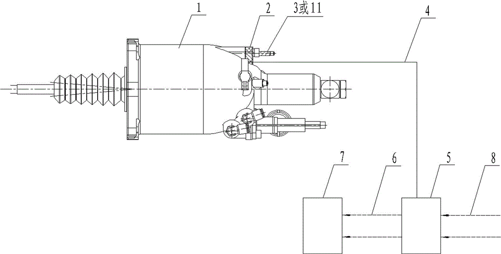
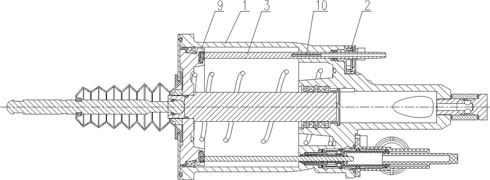
[0039] Such as figure 1 and figure 2As shown, the clutch stroke monitoring system includes a clutch booster 1, and the clutch booster 1 is equipped with a push plate 9 and a linked marking ruler 3. The left end of the linked marking ruler 3 is connected with the push plate 9, and the right end A blind hole is opened and installed at the right end of the housing of the clutch booster 1. A magnetic cylinder 10 is installed in the blind hole, and a sensor 2 is installed on the outer wall of one end of the blind hole. The sensor 2 is connected to the wiring harness 4, and the wiring harness 4 Connected with ECU5, described ECU5 is provided with input wiring harness 8 and output wiring harness 6, and output wiring harness 6 is connected with display unit and control unit 7, and display unit and control unit 7 include signal lamp, instrument panel, driving recorder and ATM, the sensor 2 adopts a displacement sensor, and the displacement sensor adopts a magnetostrictive displacemen...

Embodiment 2

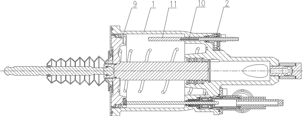
[0041] Such as figure 1 and image 3 As shown, the clutch stroke monitoring system is similar to Embodiment 1, the difference is that the linkage marking ruler 3 is replaced by the non-linkage marking ruler 11, and the left end of the non-linkage marking ruler 11 is not connected with the push plate 9, and its The right end has a blind hole and is installed on the right end of the housing of the clutch booster 1. A magnetic cylinder 10 is installed in the blind hole, and a sensor 2 is installed on the outer wall of one end of the blind hole. The sensor 2 has an external wiring harness 4, and the wiring harness 4 is connected with ECU5, and said ECU5 is provided with input wiring harness 8 and output wiring harness 6, and output wiring harness 6 is connected with display unit and control unit 7, and display unit and control unit 7 include signal indicator light, instrument panel, driving recorder and ATM, the sensor 2 adopts a displacement sensor, the displacement sensor adopt...

Embodiment 3

[0048] The clutch stroke monitoring system is similar to Embodiment 1 or 2, except that the magnetostrictive displacement sensor uses an anti-corrosion magnetostrictive displacement sensor.


PUM


Abstract

The clutch stroke monitoring system includes a clutch booster (1), on which a push plate (9) and a linked marking ruler (3) are mounted, and the left end of the linked marking ruler (3) is connected to the push plate (9), A blind hole is opened at the right end of it and installed on the right end of the housing of the clutch booster (1). The magnetic cylinder (10) is installed in the blind hole, and a sensor (2) is installed on the outer wall of one end of the blind hole. The sensor ( 2) An external wiring harness (4), the wiring harness (4) is connected to the ECU (5), and the ECU (5) is provided with an input wiring harness (8) and an output wiring harness (6). Compared with the prior art, the present invention has the beneficial effects that: the technical scheme of the present invention with the linkage marking ruler can realize the monitoring of the stroke of the clutch friction disc and timely prompt the replacement of the clutch friction disc, and can also realize the failure of the mechanical structure of the clutch and the sensor Automatically diagnose and record the clutch times and status of the clutch and provide it to the driving recorder.

Description

technical field [0001] The present invention relates to a clutch, in particular to a clutch stroke monitoring system. Background technique [0002] At present, in the field of heavy and medium-sized vehicles and commercial vehicles in China, the control part of the clutch generally adopts the control method of hydraulic control and air assist (commonly known as "liquid top gas"), that is, when the driver steps on the clutch pedal, the pedal is mechanically connected The mechanism opens the hydraulic valve of the clutch main pump to provide a certain amount of hydraulic pressure to the clutch slave pump, and the hydraulic pressure further opens the air pressure control valve of the clutch slave pump, and the push rod of the clutch booster pushes the clutch pressure plate separation mechanism under the action of gas pressure , and finally realize the disengagement and engagement of the clutch. However, the above-mentioned clutch operating system is not equipped with a monitor...

Claims


Application Information

Patent Timeline
Patent Type & Authority Patents(China)
IPC IPC(8): F16D48/06
Inventor 陈亮蒋伟荣林克詹建敏
Owner RUILI GROUP RUIAN AUTO PARTS CO LTD
Learn More