
Base plate assembly of generator set

A generator set and chassis technology, applied in the direction of the engine base, supporting machines, mechanical equipment, etc., can solve the problems of the switch bracket affecting the sensitivity, the chassis vibration resistance strength is not enough, the generator chassis is easy to loosen, etc., to protect the chassis body and structure. Simple, Intensive Effects

Inactive Publication Date: 2014-12-24
SHANGHAI HEHUA ELECTRONICS TECH
View PDF1 Cites 0 Cited by
  • Summary
  • Abstract
  • Description
  • Claims
  • Application Information

AI Technical Summary

Problems solved by technology

[0002] The generator chassis is an important part of the generator, but the traditional generator chassis is easily loosened by long-term vibration, which affects the service life, and the sensitivity of the switch bracket is affected by oil pollution. For example, the document with the application number 201120230529.4 discloses a A generator set chassis, comprising two main girders and a plurality of cross beams, a plurality of cross girders are welded in parallel at intervals between the two main girders, the main girders and cross girders are I-shaped steel, channel steel or C-shaped steel structures, and both ends of the cross girders are equipped with There is a plug, and the plug is inserted and welded with the I-beam flange groove of the main beam or the channel steel groove or the C-shaped steel C-shaped groove
The plugs at both ends of the beam are inserted and welded with the main beam I-beam flange groove or channel steel groove or C-shaped steel C-shaped groove. The welding is firm, which is conducive to improving the welding strength, ensuring the safety of the chassis and improving the service life. The chassis of the technical solution is not strong enough to withstand vibration and has a short lifespan

Method used


Image

  • Base plate assembly of generator set

Examples


Embodiment Construction

[0011] In order to make the technical means, creative features, goals and effects achieved by the present invention easy to understand, the present invention will be further described below in conjunction with specific embodiments.

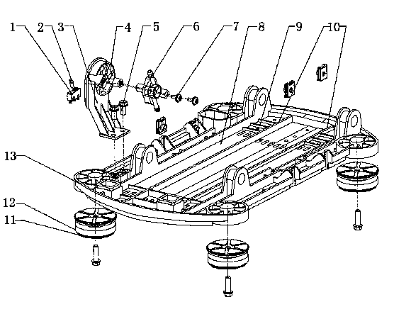
[0012] like figure 1 As shown, the generator set chassis assembly includes a chassis body 8 and an oil switch 6, the oil switch 6 is arranged on the oil switch bracket 3, and the oil switch bracket 3 is connected to the chassis body 8 through flange bolts 5, so The oil switch bracket 3 is also provided with a flameout switch 1, and the four corners of the chassis body 8 are provided with feet 12, and the chassis body 8 is provided with two reinforcing ribs 10, and beside the reinforcing ribs 10, there are There are several draw-in slots 9, the draw-in slots 9 are arranged on the chassis body 8, the filter screen 4 is provided on the oil switch bracket 3, the cover sheet 2 is provided on the flame-out switch 1, and two reinforcing ribs can Effect...


PUM


Abstract

The invention discloses a base plate assembly of a generator set, and relates to the field of generator accessories. The base plate assembly comprises a base plate body and an oil switch. The oil switch is arranged on an oil switch support. The oil switch support is connected to the base plate body through flange bolts. A flameout switch is arranged on the oil switch support. Feet are arranged at four corners of the base plate body. Two reinforcing ribs are arranged on the base plate body. A plurality of clamping grooves are formed beside the reinforcing ribs and in the base plate body. A strainer is arranged on the oil switch support. A cover plate is arranged on the flameout switch. By the reinforcing ribs, the strength of the base plate body and shock resistance can be effectively improved; by the clamping grooves, the base plate body can be fastened with a generator, so that tight connection is achieved; by the strainer, sensitivity reduction caused by contamination of the oil switch support can be avoided; by the cover plate arranged on the flameout switch, contamination prevention is also realized.

Description

technical field [0001] The invention relates to the field of generator accessories, in particular to a chassis assembly of a generator set. Background technique [0002] The generator chassis is an important part of the generator, but the traditional generator chassis is easily loosened by long-term vibration, which affects the service life, and the sensitivity of the switch bracket is affected by oil pollution. For example, the document with the application number 201120230529.4 discloses a A generator set chassis, comprising two main girders and a plurality of cross beams, a plurality of cross beams are welded in parallel at intervals between the two main girders, the main girders and cross beams are I-shaped steel, channel steel or C-shaped steel structures, and the two ends of the cross beams are equipped with There is a plug, and the plug is inserted and welded with the I-shaped steel flange groove of the main beam or the groove of the channel steel or the C-shaped groo...

Claims


Application Information

Patent Timeline
IPC IPC(8): F16M5/00F16F15/08
Inventor 郑小坚郭炎铭
Owner SHANGHAI HEHUA ELECTRONICS TECH
Learn More