High-precision current sensor detecting circuit and detecting method thereof

A current sensor and detection circuit technology, applied in the direction of using digital measurement technology for measurement, can solve the problems affecting measurement accuracy, small current change, low output voltage resolution, etc., to achieve good linearity and dynamic performance, and wide operating frequency bandwidth. , the effect of high measurement accuracy

Active Publication Date: 2014-12-24
武汉弈飞科技有限公司
View PDF6 Cites 24 Cited by
  • Summary
  • Abstract
  • Description
  • Claims
  • Application Information

AI Technical Summary

Problems solved by technology

[0003] Therefore, the output linearity of the Hall current sensor is mainly affected by the non-linearity of the magnetic core permeability. When the magnetic field strength increases, its output voltage no longer increases, which affects the measurement accuracy
On the contrary, when the change of the magnetic field is not obvious, the change of the output voltage is relatively small. In this case, when the change of the current is small, the change of the output voltage is not obvious, and it is easy to cause measurement errors.
[0004] In the application process of electric vehicles, when the current flowing through the wire changes by hundreds of amperes, a magnetic core and a Hall element related to the magnetic induction intensity are used, and the output voltage changes linearly, which can reflect the current real current change; When the electric vehicle is in static operation, the main driver has no output, and its operating current varies around ±10-35A. Not obvious, the current output voltage resolution is low, it cannot truly reflect current changes, and there are obvious deviations in SOC statistics, resulting in large current accumulation errors

Method used


Image

  • High-precision current sensor detecting circuit and detecting method thereof
  • High-precision current sensor detecting circuit and detecting method thereof
  • High-precision current sensor detecting circuit and detecting method thereof

Examples


Embodiment Construction

[0021] The present invention will be further described below in conjunction with the accompanying drawings and specific embodiments.

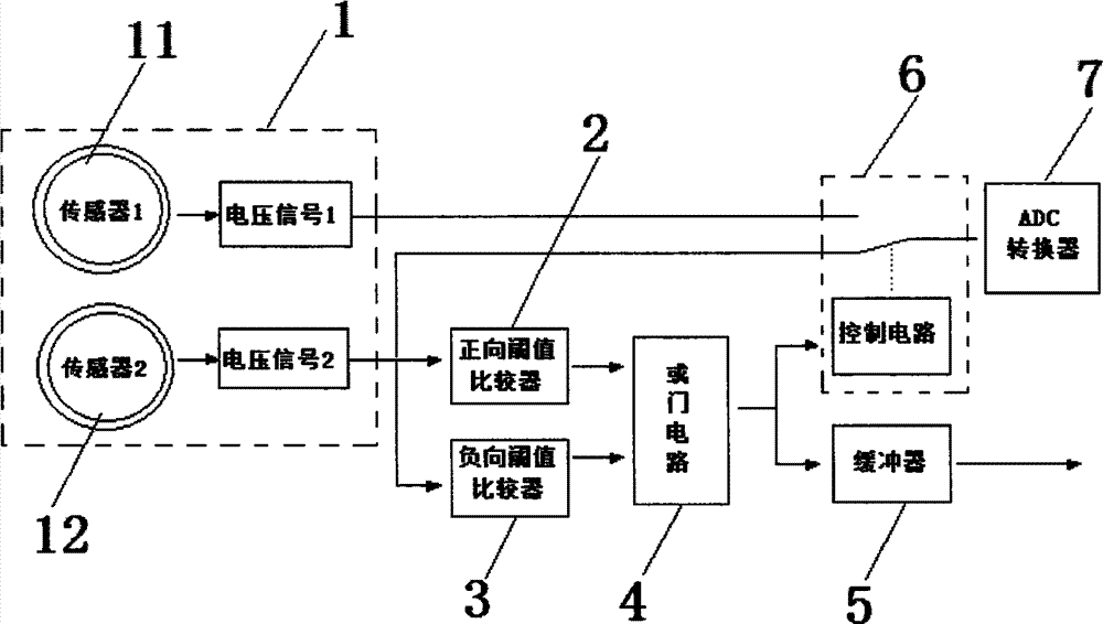
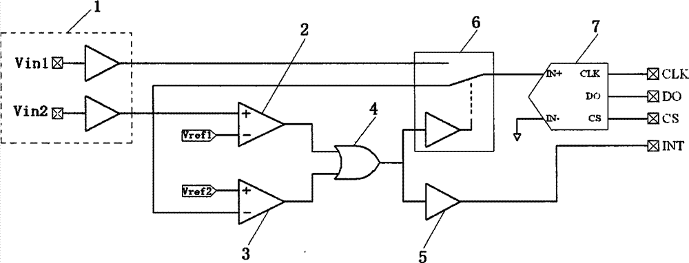
[0022] Such as figure 1 , figure 2 As shown, a high-precision current sensor detection circuit is used to detect the charging and discharging current of the electric vehicle power battery system, including a combined magnetoelectric conversion unit 1, a positive threshold comparator 2, a negative threshold comparator 3, and an OR gate circuit 4. Output buffer 5, SPDT analog switch 6 and ADC converter 7. The combined magnetoelectric conversion unit 1 is composed of a first Hall current sensor 11 with a larger range and a second Hall current sensor 12 with a smaller range. Single pole double throw analog switch 6 selects ADG849 analog switch.

[0023] The output end of the first Hall current sensor 11 is connected to the normally open contact of the SPDT analog switch 6, the output end of the second Hall current sensor 12 is connected to the ...


PUM


Abstract

The invention provides a high-precision current sensor detecting circuit which comprises a combined magnetoelectricity conversion unit, a positive threshold comparator, a negative threshold comparator, an OR gate circuit, an output buffer, an analog switch and an ADC (analog-to-digital converter). The combined magnetoelectricity conversion unit comprises a large-range first current sensor and a small-range second current sensor. The output end of the first current sensor is connected to the input end of the ADC through the normally open contact of the analog switch. The output end of the second current sensor is connected to the input end of the ADC through the normally closed contact of the analog switch. The output end of the ADC is connected with the input end of a post-stage circuit. The invention further provides a detecting method of the high-precision current sensor detecting circuit. The high-precision current sensor detecting circuit is wide in measuring range, fast in response, high in measuring precision, good in linearity and dynamic performance, wide in working band, high in reliability, high in overload capacity, and the like.

Description

technical field [0001] The invention relates to the technical field of charging and discharging current detection of electric vehicle power battery systems, in particular to a high-precision current sensor detection circuit and a detection method thereof. Background technique [0002] At present, the isolation detection of the charge and discharge current of the electric vehicle power battery system often adopts the Hall sampling method. The Hall sampling method uses a Hall current sensor for current sampling. The Hall current sensor is based on the magnetic balance Hall principle, that is, the closed-loop principle. The magnetic flux generated by the primary current is concentrated in the magnetic circuit through a high-quality magnetic core. The element is fixed in the air gap to detect the magnetic flux. After processing by a special circuit, the output terminal of the Hall current sensor can output a voltage signal that accurately reflects the change of the primary curre...

Claims


Application Information

Patent Timeline
Patent Type & Authority Applications(China)
IPC IPC(8): G01R19/25
Inventor 徐青吴嘉熙
Owner 武汉弈飞科技有限公司
Why Eureka
Try Eureka